Machine head of embroidery machine and embroidery machine

A technology of embroidery machine and machine head, which is applied in the field of embroidery machines, and can solve problems such as motor running power not meeting driving requirements, uncontrollable spring force, and restricting presser foot speed, so as to improve embroidery quality, avoid interference, and rationalize structural settings Effect

Pending Publication Date: 2021-04-16
ZHEJIANG XINSHENG SEWING EQUIP
View PDF0 Cites 0 Cited by
  • Summary
  • Abstract
  • Description
  • Claims
  • Application Information

AI Technical Summary

Problems solved by technology

In the first type of presser foot driving structure, the elastic force of the spring is uncontrollable, which restricts the speed of the presser foot when it moves up and down
In the second type of presser foot driving structure, the motor adopts the way of swinging up and down, and the operating power of the motor cannot meet the driving requirements of the increasing number of machine heads on the market.

Method used


Image

  • Machine head of embroidery machine and embroidery machine
  • Machine head of embroidery machine and embroidery machine
  • Machine head of embroidery machine and embroidery machine

Examples


Embodiment 1

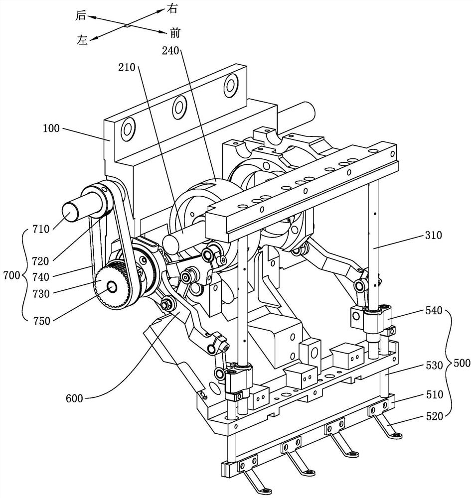
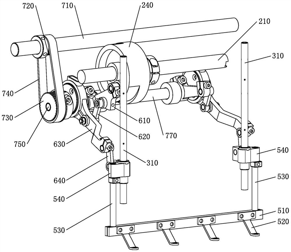
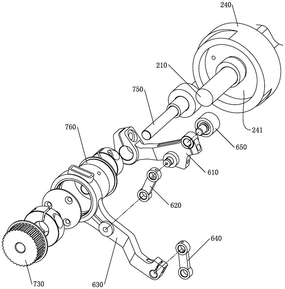
[0036] Such as Figure 1 to Figure 7 As shown, Embodiment 1 of the present invention provides an embroidery machine head, including a casing 100, a needle bar driving shaft 210 rotatably placed horizontally on the casing, and a needle bar cam eccentrically sleeved on the needle bar driving shaft. 220, the guide rod 310 vertically placed on the casing, the needle bar driver 320 sleeved on the guide rod, the connecting rod structure 400 arranged between the needle bar cam and the needle bar driver, and the eccentric sleeve set on the needle bar drive shaft presser foot drive wheel 240 on the The machine head also includes a presser foot mechanism 500, a presser foot transmission mechanism 600 and a presser foot adjustment mechanism 700. The presser foot mechanism 500 includes a presser foot bar 510, a presser foot 520 and a presser foot lifting rod 530. The presser foot bar 510 is placed horizontally on the machine casing. At the bottom of 100 , a plurality of presser feet 520 ...


PUM


Abstract

The invention discloses a machine head of an embroidery machine head and the embroidery machine, and belongs to the technical field of embroidery machines. The machine head of the embroidery machine head comprises a machine shell, a needle rod driving shaft, a needle rod cam, a guide rod, a needle rod driver, a connecting rod structure, a presser foot driving wheel, a presser foot mechanism, a presser foot transmission mechanism and a presser foot adjusting mechanism, wherein the presser foot mechanism comprises a presser foot strip, presser feet and a presser foot lifting rod; the presser foot strip is transversely arranged at the bottom of the machine shell; the presser feet are arranged on the presser foot strip at intervals in the transverse direction; the presser foot lifting rod is vertically arranged on the machine shell, and the bottom end of the presser foot lifting rod is connected to the presser foot strip; the presser foot transmission mechanism is arranged between the presser foot driving wheel and the presser foot lifting rod, and used for driving the presser foot mechanism to move up and down; and the presser foot adjusting mechanism is arranged on the machine shell and adjusts the vertical position of the presser foot mechanism through the presser foot transmission mechanism. The presser foot adjusting mechanism can adjust the vertical position of the presser foot mechanism through the presser foot transmission mechanism, the presser foot mechanism can be lifted conveniently in the states of embroidery cloth replacement, shutdown and the like, and the presser foot mechanism is prevented from interfering with embroidery cloth replacement and other operations.

Description

technical field [0001] The invention relates to the technical field of embroidery machines, in particular to an embroidery machine head. In addition, the invention also relates to an embroidery machine using the embroidery machine head. Background technique [0002] With the advancement of science and technology, computerized embroidery machines have now become the main mechanical equipment in the embroidery industry, and the head of the embroidery machine is an important structure of the embroidery machine. The drive structure of the presser foot of the existing lace embroidery machine is mainly divided into two types, one is the structure of a unilateral open cam plus a spring, and the other is a structure of a motor plus a connecting rod mechanism. These two drive mechanisms have their own Shortcomings. In the first type of presser foot driving structure, the elastic force of the spring is uncontrollable, which restricts the speed of the presser foot when it moves up and...

Claims


Application Information

Patent Timeline
IPC IPC(8): D05C9/20D05C11/06
Inventor 王海江田桂郁
Owner ZHEJIANG XINSHENG SEWING EQUIP
Why Eureka
Try Eureka