PC-grade large-current dual-power automatic change-over switch

An automatic transfer switch, dual power supply technology, applied in emergency power supply arrangements, power devices inside the switch, electrical components, etc., can solve the problem that the working stability needs to be improved, the action speed of the dual power automatic transfer switch does not meet the requirements, and the action torque minor issues

Pending Publication Date: 2021-04-16
BEIJING MINGRI ELECTRICAL EQUIP
View PDF0 Cites 0 Cited by
  • Summary
  • Abstract
  • Description
  • Claims
  • Application Information

AI Technical Summary

Problems solved by technology

Generally, the dual power automatic transfer switch has a lever action mechanism and a contact arc extinguishing mechanism. Due to the limitation of the structure of the lever action mechanism and the contact arc extinguishing mechanism of the traditional PC-level dual power automatic transfer switch, the transmitted action torque is small, and at the same time The action speed of the dual-power automatic transfer switch cannot meet the requirements during power conversion. When the dual-power automatic transfer switch performs power conversion, especially when the high-current power conversion is performed, it is not enough to push the contacts to move quickly so that the dual-power automatic transfer switch can be carried out smoothly. Power conversion, while working stability needs to be improved

Method used


Image

  • PC-grade large-current dual-power automatic change-over switch
  • PC-grade large-current dual-power automatic change-over switch
  • PC-grade large-current dual-power automatic change-over switch

Examples


Embodiment Construction

[0047] First of all, it should be noted that the orientation or positional relationship indicated by the terms "upper", "lower", "left", "right", "inner", "outer" and so on is based on the orientation or positional relationship shown in the drawings , is only for the convenience of describing the present invention and simplifying the description, but does not indicate or imply that the referred device or part must have a specific orientation, be constructed and operated in a specific orientation, and thus should not be construed as limiting the present invention. In addition, the terms "common power supply" and "backup power supply" are only used to describe the location on the drawing, and should not be understood as indicating or implying the inherent characteristic names of the location in actual use.

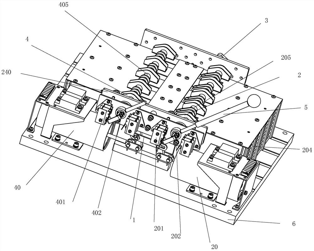
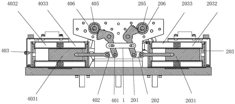
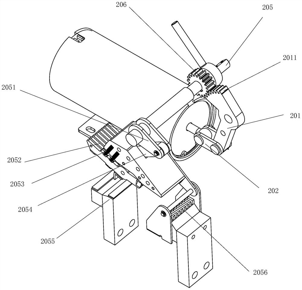
[0048] Below, combine Figure 1 to Figure 14 , the present invention will be further described through specific examples.

[0049] Such as Figure 1 ~ Figure 3 As shown, a...


PUM


Abstract

The invention provides a PC-level large-current dual-power-supply automatic change-over switch, which comprises electromagnet driving mechanisms and a contact arc extinguishing mechanism, wherein the two electromagnet driving mechanisms are symmetrically arranged for three-section working, only one electromagnet driving mechanism is needed for two-section working, a driving electromagnet is provided with a thrust coil and a tension coil, a movable iron core pushes or pulls a gear transmission lever to perform action conversion, a contact four-connecting-rod mechanism is arranged on an action rotating shaft of a common power supply and an action rotating shaft of a standby power supply, an action interlocking device is arranged between the two action rotating shafts so as to obtain quick and large transmission torque on the action rotating shafts of the dual-power-supply automatic change-over switch, and due to the action of the four-connecting-rod mechanism and the interlocking device, stable work of the dual power supply under various working conditions can be ensured, so that the dual-power-supply automatic change-over switch with a simple structure and stable performance is suitable for power supply change-over under large current.

Description

[0001] The invention relates to a low-voltage electrical appliance, in particular to a PC-level high-current dual-power automatic transfer switch. Background technique [0002] Dual power automatic transfer switch is a commonly used low-voltage electrical appliance, which is often used to switch between two power sources, so as to ensure that when one power source fails or stops supplying power, the other power source can be quickly switched to ensure the normal power supply of the load circuit. . Generally, the dual power automatic transfer switch has a lever action mechanism and a contact arc extinguishing mechanism. Due to the limitation of the structure of the lever action mechanism and the contact arc extinguishing mechanism of the traditional PC-level dual power automatic transfer switch, the transmitted action torque is small, and at the same time The action speed of the dual-power automatic transfer switch cannot meet the requirements during power conversion. When the ...

Claims


Application Information

Patent Timeline
Patent Type & Authority Applications(China)
IPC IPC(8): H01H3/28H01H3/32H01H3/38H01H3/46H02J9/06
Inventor 冷岩王辉
Owner BEIJING MINGRI ELECTRICAL EQUIP
Why Eureka
Try Eureka