
Internet-of-Things switch heat dissipation structure device

A heat dissipation structure and switch technology, which is applied in the field of switches, can solve problems such as poor heat dissipation effect and inability to effectively remove heat from switches, and achieve the effects of improving heat dissipation performance, improving heat dissipation effect, and improving work performance

Inactive Publication Date: 2021-04-16
南京迪梵安家具有限公司
View PDF0 Cites 0 Cited by
  • Summary
  • Abstract
  • Description
  • Claims
  • Application Information

AI Technical Summary

Problems solved by technology

[0004] Aiming at the deficiencies of the prior art, the present invention provides a heat dissipation structure device for an Internet of Things switch, which solves the problem that the heat of the switch cannot be effectively removed and the heat dissipation effect is poor

Method used


Image

  • Internet-of-Things switch heat dissipation structure device
  • Internet-of-Things switch heat dissipation structure device
  • Internet-of-Things switch heat dissipation structure device

Examples


Embodiment 1

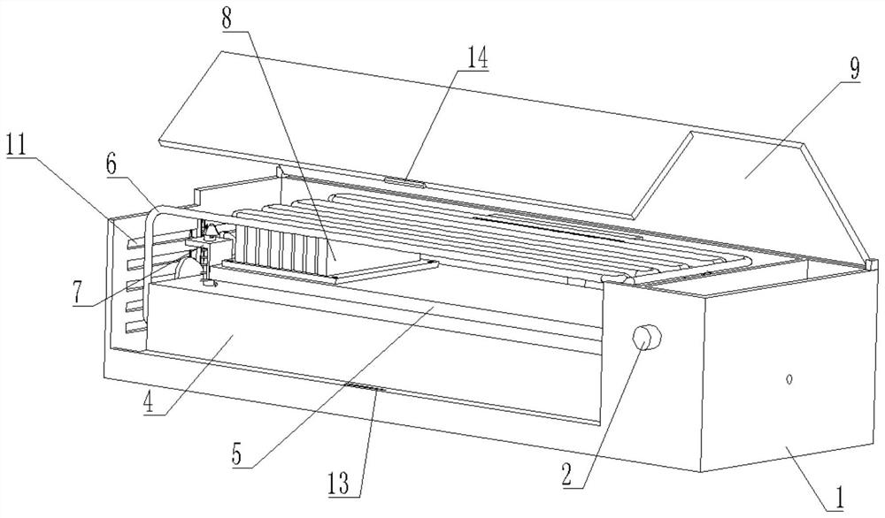
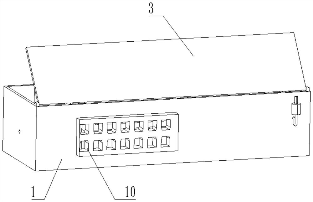
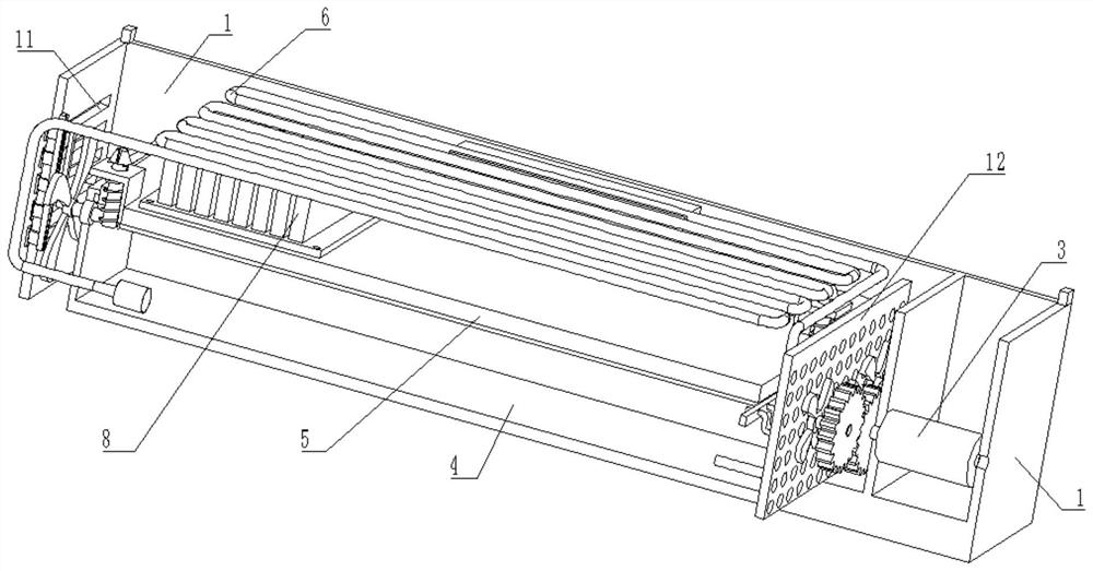
[0031] see Figure 1-6 , a heat dissipation structure device for an Internet of Things switch, comprising a housing 1, a switch button 2 is fixedly installed on the front of the housing 1, a water tank 4 is fixedly connected to the bottom wall inside the housing 1, and a driving mechanism is arranged inside the housing 1 3. The upper surface of the housing 1 is rotatably connected with a flip cover 9, the rear of the housing 1 is fixedly installed with a plug-in terminal 10, the inside of the housing 1 is provided with a main board 5, and the upper surface of the main board 5 is fixedly installed with a heat sink 8, The top of the main board 5 is provided with a fixing mechanism 7 , the interior of the water tank 4 is provided with a heat dissipation mechanism 6 , and the left side of the housing 1 is provided with a heat dissipation groove 11 .

[0032] In this embodiment, a key 14 is fixedly connected to the lower surface of the flip cover 9 , a slot 13 is opened on the surf...

Embodiment 2

[0045] see Figure 7-8 , on the basis of Embodiment 1, in this embodiment, the fixing mechanism 7 includes a fixing column 72, the bottom of the fixing column 72 is fixedly connected to the upper surface of the water tank 4, and the upper surface of the fixing column 72 is provided with a T-shaped groove. The upper surface of the column 72 is slidably connected with a tapered block 74, and the surface of the fixed column 72 is slidably connected with a slide plate 71. The tight spring 73 is positioned under the slide plate 71 .

[0046] The main board 5 is inserted into the diagonal fixing mechanism 7, because the set conical block 74 of the tapered structure allows the main board 5 to be easily inserted into the fixing column 72, so that the installation of the main board 5 is very convenient and fast.

[0047] In this embodiment, the number of conical blocks 74 is provided with three, and the inner walls of the three conical blocks 74 are fixedly connected with arc springs ...


PUM


Abstract

The invention relates to the technical field of switches, and discloses an Internet-of-Things switch heat dissipation structure device which comprises a shell, a switch button is fixedly installed on the front portion of the shell, a water tank is fixedly connected to the bottom wall of the interior of the shell, a driving mechanism is arranged in the shell, and a flip cover is rotatably connected to the upper surface of the shell. A plug wire end is fixedly mounted at the rear part of the shell, a main board is arranged in the shell, cooling fins are fixedly mounted on the upper surface of the main board, a fixing mechanism is arranged at the top of the main board, a cooling mechanism is arranged in the water tank, and a cooling groove is formed in the left side of the shell. According to the heat dissipation structure device of the Internet-of-Things switch, heat is dissipated at the same time through the exchangeability of air cooling and water cooling, so that the effect of efficient air cooling and heat dissipation of the switch is achieved, the overall working performance of the switch is improved, the overall heat dissipation performance of the switch is improved, and the network operation speed of the switch is increased.

Description

technical field [0001] The invention relates to the technical field of switches, in particular to a cooling structure device for an Internet of Things switch. Background technique [0002] A switch is a network device used for electrical signal forwarding. It can provide an exclusive electrical signal path for any two network nodes connected to the switch. The most common switches are Ethernet switches. Other common ones are telephone voice switches, fiber optic switches, etc. [0003] At present, many switches cannot efficiently remove heat from the switch, because the heat caused by the high-intensity work of the motherboard cannot be dissipated quickly, resulting in easy heat concentration, causing damage to the internal motherboard of the switch, and affecting the speed of the network. As a result, the performance of the switch is affected, so a heat dissipation structure device for an Internet of Things switch is proposed to solve the above-mentioned problem. Conte...

Claims


Application Information

Patent Timeline
Patent Type & Authority Applications(China)
IPC IPC(8): H04Q1/02H04Q1/10B08B1/00B01D46/10
Inventor 不公告发明人
Owner 南京迪梵安家具有限公司
Learn More