Spiral conveying assembly and solid-liquid separation equipment
What is Al technical title?
Al technical title is built by PatSnap Al team. It summarizes the technical point description of the patent document.
A technology of screw conveying and components, applied in the field of solid-liquid separation equipment, can solve the problems of low efficiency of solid-liquid separation
Active Publication Date: 2021-04-20
NANJING AGRI MECHANIZATION INST MIN OF AGRI
View PDF13 Cites 1 Cited by
Summary
Abstract
Description
Claims
Application Information
AI Technical Summary
This helps you quickly interpret patents by identifying the three key elements:
Problems solved by technology
Method used
Benefits of technology
Problems solved by technology
[0004] The purpose of the present invention is to provide a screw conveying assembly and solid-liquid separation equipment to solve the technical problem of low solid-liquid separation efficiency in the prior art
Method used
Image
Click on the blue label to locate the original text in one second.
Reading with bidirectional positioning of images and text.
Examples
Embodiment 1
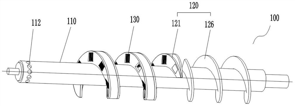
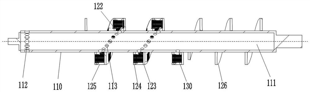
[0044] like figure 1 , figure 2 and image 3 As shown, a screw conveying assembly 100 provided in this embodiment includes a rotating shaft 110 and a screw blade assembly 120 , the screw blade assembly 120 is arranged on the rotating shaft 110 , and the rotating shaft 110 drives the screw blade assembly 120 to rotate.
[0045] Wherein, the rotating shaft 110 adopts a hollow shaft, and the interior of the rotating shaft 110 is provided with a water collection chamber 111 for collecting the liquid produced by the material. the liquid in the water cavity 111;
[0046] The spiral blade assembly 120 includes a hollow blade 121. The hollow blade 121 is provided with a plurality of installation holes 122 along the material conveying direction. The installation holes 122 communicate with the inner cavity of the hollow blade 121. The rotating shaft 110 is provided with a plurality of water holes 113 for communication. The inner cavity and the water collecting cavity 111, a pluralit...
Embodiment 2
[0061] like Figure 4 , Figure 5 , Image 6 and Figure 7 As shown, a solid-liquid separation device provided in this embodiment includes a housing 200, a water collector 300, a separation screen 400, a fixing frame 500, and the screw conveying assembly 100 in the first embodiment above;
[0062] It should be noted that, since the structure and working principle of the screw conveying assembly 100 have been described in the first embodiment, please refer to the technical solution of the first embodiment for the screw conveying assembly 100 involved in this embodiment.
[0063] In this embodiment, the housing 200 is provided with a material conveying cavity along the axial direction, and the material conveying cavity is divided into a connected feeding section 210 and a feeding section 220 along the material conveying direction;
[0064] The screw conveying assembly 100 is arranged in the material conveying cavity, the separating screen 400 is arranged in the conveying sect...
PUM
Abstract
The invention provides a spiral conveying assembly and solid-liquid separation equipment, the spiral conveying assembly comprises a rotating shaft and a spiral blade assembly, the rotating shaft is a hollow shaft and is internally provided with a water collecting cavity, and the shaft wall of the rotating shaft is provided with a drainage hole communicated with the water collecting cavity; the spiral blade assembly comprises a hollow blade, a plurality of mounting holes are formed in the hollow blade in the material conveying direction, the mounting holes communicate with an inner cavity of the hollow blade, and a plurality of water through holes are formed in the rotating shaft and used for communicating the inner cavity with the water collecting cavity; the spiral conveying assembly further comprises a plurality of filtering assemblies, the filtering assemblies are arranged in the mounting holes, and a plurality of filtering channels communicating with the inner cavity and the external environment are formed in the filtering assemblies; by the adoption of the technical scheme, the spiral blades are matched with the rotating shaft, the functions of material conveying and solid-liquid separation are achieved at the same time, then the solid-liquid separation efficiency of materials can be effectively improved, and the solid-liquid separation equipment comprises the spiral conveying assembly.
Description
technical field [0001] The invention relates to the field of solid-liquid separation equipment, in particular to a screw conveying component and solid-liquid separation equipment. Background technique [0002] The existing auger-type solid-liquid separation equipment is suitable for the excrement treatment of various farmed livestock and poultry, and its structure usually includes a shell, a separating screen, an auger and other parts. There are still many problems in the current solid-liquid separation equipment, such as the adaptability to materials and the efficiency of solid-liquid separation. In particular, improving the separation efficiency has always been the research goal of relevant technical personnel. [0003] At present, the optimization and improvement schemes for solid-liquid separation equipment generally focus on the research and improvement of the auger. For example, in the document with the application number CN201921573628.5, the blades of the auger are ...
Claims
Application Information
Patent Timeline
Application Date:The date an application was filed.
Publication Date:The date a patent or application was officially published.
First Publication Date:The earliest publication date of a patent with the same application number.
Issue Date:Publication date of the patent grant document.
PCT Entry Date:The Entry date of PCT National Phase.
Estimated Expiry Date:The statutory expiry date of a patent right according to the Patent Law, and it is the longest term of protection that the patent right can achieve without the termination of the patent right due to other reasons(Term extension factor has been taken into account ).
Invalid Date:Actual expiry date is based on effective date or publication date of legal transaction data of invalid patent.