Electric cutting tool

A cutting tool, electric technology, applied in the direction of manufacturing tools, shearing devices, metal processing equipment, etc., can solve the problem of fixed cutting target, and achieve the effect of accurate cutting, improved flatness, and stable fixation

Active Publication Date: 2021-04-20
南京庚鼠科技有限公司
View PDF5 Cites 0 Cited by
  • Summary
  • Abstract
  • Description
  • Claims
  • Application Information

AI Technical Summary

Problems solved by technology

[0004] Aiming at the deficiencies of the prior art, the present invention provides an electric cutting tool, which solves the problem of fixing the cutting target

Method used


Image

  • Electric cutting tool
  • Electric cutting tool
  • Electric cutting tool

Examples


Embodiment 1

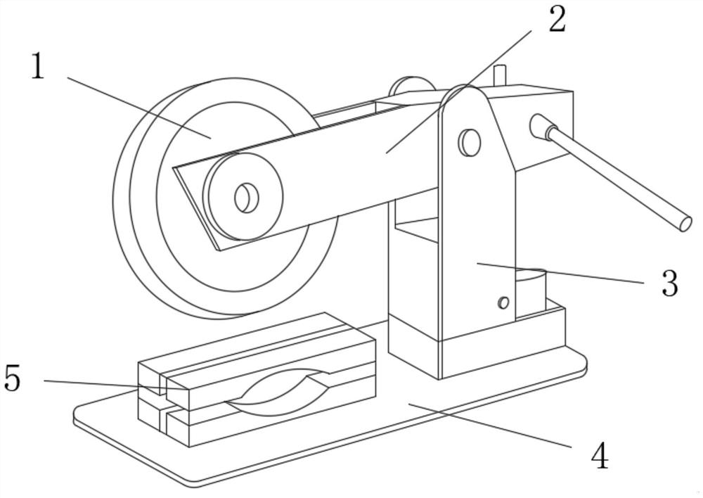
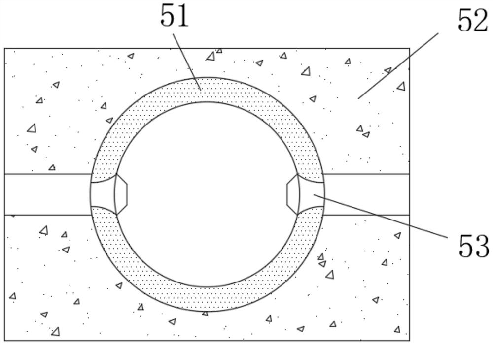
[0030] Such as Figure 1-3 As shown, the present invention provides a technical solution: an electric cutting tool, including a bottom plate 4, the right side of the upper surface of the bottom plate 4 is fixedly connected with a support column 3, and the top of the support is rotatably connected with a lower pressing arm 2, The left end of the lower pressing arm 2 is rotatably connected with a cutting disc 1, and the upper surface of the bottom plate 4 is fixedly connected with a fixing device 5, and the fixing device 5 is arranged directly below the cutting disc 1, and the fixing device 5 includes a fixing block 52, the number of the fixed blocks 52 is two, and the two fixed blocks 52 are stacked up and down, and the feature is that: the depressions on the opposite surfaces of the fixed blocks 52 are fixedly connected with extrusion pockets 51 , the left and right ends of the squeeze bag 51 are movably connected with a pressure device 53, the left and right ends of the squee...

Embodiment 2

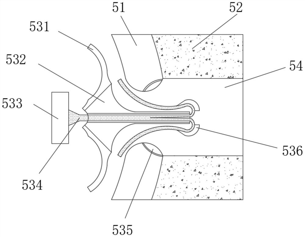
[0033] Such as Figure 4-6 As shown, on the basis of Embodiment 1, the present invention provides a technical solution: the blocking device 536 includes a rubber shell 5363 and an elastic rubber block 5361, and the rubber shell 5363 and the elastic rubber block 5361 are fixedly connected to the special-shaped The surface of the elastic iron rod 534, the elastic rubber block 5361 is fixedly connected to the inside of the rubber shell 5363, the outer surface of the elastic rubber block 5361 is provided with a groove 5364, and the surface of the rubber shell 5363 is fixedly connected with a buckle lock device 5362, and the locking device 5362 is symmetrically arranged at both ends of the groove 5364, and the special-shaped elastic iron rod 534 moves to the right, so that the special-shaped elastic iron rod 534 flattens and shrinks the elastic rubber block 5361, so that the space in the groove 5364 becomes larger , when the blocking device 536 contacts the extrusion bag 51, the gr...

Embodiment 3

[0037] Such as Figure 7 As shown, on the basis of Embodiment 1 and Embodiment 2, the present invention provides a technical solution: the docking device 533 includes a docking block 5332, a slide bar 5333 and a pressing block 5335, and the right end of the docking block 5332 is aligned with the special-shaped The left end of the elastic iron rod 534 is fixedly connected, and the inside of the docking block 5332 is provided with a sliding hole 5331. The sliding rod 5333 penetrates the docking block 5332 through the sliding hole 5331 and extends to the upper and lower ends of the left side. The two ends of the sliding rod 5333 Both are rotatably connected with a rotating shaft 5336, the upper end of the sliding rod 5333 is rotatably connected with the upper end of the pressing block 5335 through the rotating shaft 5336, and the upper end of the sliding rod 5333 is fixedly connected with the pressing block 5335 through the elastic block 5334, the There are three pressing blocks ...


PUM


Abstract

The invention discloses an electric cutting tool and relates to the technical field of electric tools. The electric cutting tool comprises a bottom plate, a supporting column is fixedly connected to the right side of the upper surface of the bottom plate, a pressing arm is rotationally connected to the top of the supporting column, a cutting disc is rotationally connected to the left end of the pressing arm, a fixing device is fixedly connected to the upper surface of the bottom plate, and the fixing device is arranged under the cutting disc. The fixing device comprises two fixing blocks, the two fixing blocks are stacked up and down, an extrusion bag is fixedly connected between the concave positions of the opposite faces of the fixing blocks, and the left end and the right end of the extrusion bag are movably connected with pressure devices. According to a cutting machine fixing device, the effect that the extrusion bag fixes an internal cutting target is achieved by pressing the fixing block on the upper side, meanwhile, during cutting operation, the extrusion bag can relieve shaking of the cutting disc, so that the cutting target is cut more stably, and the cutting efficiency is improved.

Description

technical field [0001] The invention relates to the technical field of electric tools, in particular to an electric cutting tool. Background technique [0002] The cutting machine is a powerful cutting machine, which is used in the metal and non-metal industries. With the development of the modern mechanical processing industry, the cutting machine is used as a basic machine. Based on the above description, the inventor found that an existing 5G communication base station mainly There are deficiencies such as: [0003] Due to the continuous improvement of cutting quality and precision requirements, the requirements for improving production efficiency, reducing production costs, and highly intelligent automatic cutting functions are also increasing. , or because the cutting disc shakes violently when cutting the target, which causes the target section to be not smooth after cutting by the cutting machine, and the error is large. As a result, the cutting effect of the cuttin...

Claims


Application Information

Patent Timeline
Patent Type & Authority Applications(China)
IPC IPC(8): B23D33/02B23D19/00B23D33/00
CPCY02P70/10
Inventor 李玉霞
Owner 南京庚鼠科技有限公司
Why Eureka
Try Eureka