
Part clamping and fixing device based on machine manufacturing

A mechanical manufacturing, clamping and fixing technology, applied in workpiece clamping devices, manufacturing tools, etc., can solve problems such as excessive clamping of parts, insufficient stability, and processing failure.

Inactive Publication Date: 2021-04-20
宁波金日机床有限公司
View PDF5 Cites 0 Cited by
  • Summary
  • Abstract
  • Description
  • Claims
  • Application Information

AI Technical Summary

Problems solved by technology

Mechanical parts need to be polished, cut, drilled, polished, etc. during production, and they need to be clamped and fixed before processing. Most of the clamping and fixing devices of existing processing equipment need manual adjustment, and the degree of automation is not enough. High, and manual adjustment is not easy to control the clamping force, prone to excessive clamping or insufficient stability of parts, which will lead to damage to parts or deviation of parts during processing; in addition, general clamping devices can only hold Or cylinders and other parts with specific shapes are clamped and fixed. When processing some irregular parts, the clamping and fixing effect of such devices is not ideal. The parts are easy to loose during processing, resulting in processing failure and material waste of
[0003] Aiming at the deficiencies of the prior art, the present invention provides a clamping and fixing device for parts based on mechanical manufacturing, which has the advantages of high degree of automation, prevention of excessive clamping, more stable clamping and clamping and fixing of irregular parts It solves the problems that the general clamping and fixing device has a small application range and the clamping and fixing effect is not ideal.

Method used


Image

  • Part clamping and fixing device based on machine manufacturing
  • Part clamping and fixing device based on machine manufacturing
  • Part clamping and fixing device based on machine manufacturing

Examples


Embodiment Construction

[0022] The following will clearly and completely describe the technical solutions in the embodiments of the present invention with reference to the accompanying drawings in the embodiments of the present invention. Obviously, the described embodiments are only some, not all, embodiments of the present invention. Based on the embodiments of the present invention, all other embodiments obtained by persons of ordinary skill in the art without making creative efforts belong to the protection scope of the present invention.

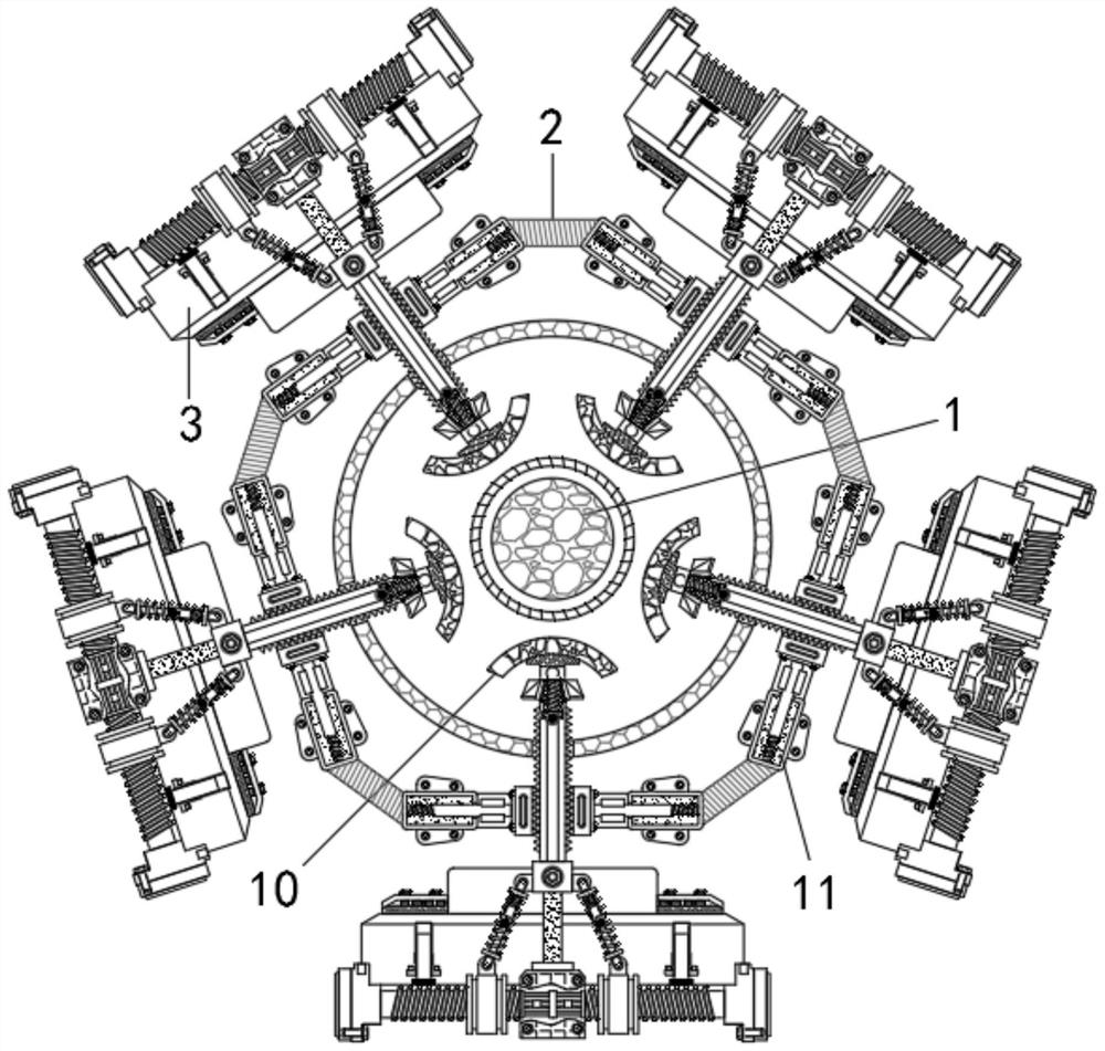
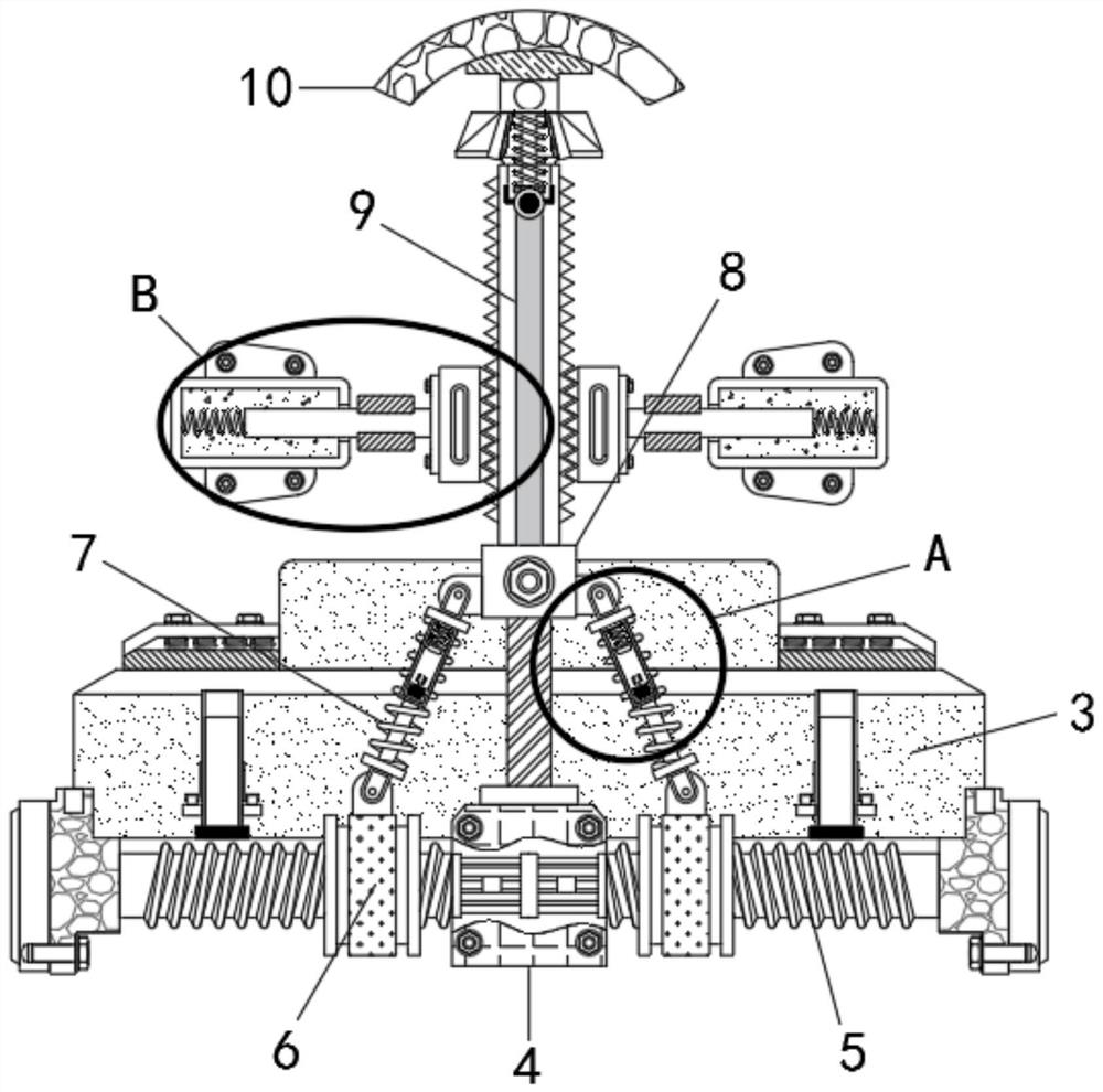
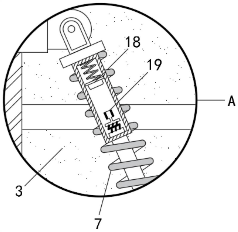
[0023] see Figure 1-4 , a clamping and fixing device for components based on mechanical manufacturing, including a placement table 1, an installation bracket 2 is arranged on the outside of the placement table 1, an equipment main body 3 is arranged on the outside of the installation bracket 2, and a two-way The output end of the driving device 4 and the bidirectional driving device 4 are all provided with a threaded rod 5, the body of the threaded rod 5 is t...


PUM


Abstract

The invention relates to the technical field of machine manufacturing, and discloses a part clamping and fixing device based on machine manufacturing. The part clamping and fixing device comprises a placing table, a mounting bracket is arranged on the outer side of the placing table, an equipment main body is arranged on the outer side of the mounting bracket, and a bidirectional driving device is arranged in the middle of the equipment main body. According to the part clamping and fixing device based on machine manufacturing, after an electric plug abuts against an electric socket, electrorheological fluid is electrified and is changed into a solid state from a suspension state, the positions of a guide rod and a mounting block are fixed, the mounting block limits a push rod through sawteeth, the push rod and clamping devices cannot move, and the clamping devices and the push rod are prevented from being loosened due to vibration during machining, so that the part is clamped more stably; the at least five clamping devices are annularly arranged with the placing table used as the center, the part can be clamped and fixed in different directions, movement of the clamping devices does not affect one another, and thus the pars with the irregular shape can be clamped and fixed.

Description

technical field [0001] The invention relates to the technical field of mechanical manufacturing, in particular to a clamping and fixing device for components based on mechanical manufacturing. Background technique [0002] Machinery manufacturing refers to the industry engaged in the production of various power, chemical, transportation, textile and other machinery, as well as machine tools, tools, instruments, meters and other mechanical equipment. The mechanical products produced through machinery manufacturing include components, sub-components and parts. Mechanical parts need to be polished, cut, drilled, polished, etc. during production, and they need to be clamped and fixed before processing. Most of the clamping and fixing devices of existing processing equipment need manual adjustment, and the degree of automation is not enough. High, and manual adjustment is not easy to control the clamping force, prone to excessive clamping or insufficient stability of parts, which...

Claims


Application Information

Patent Timeline
Patent Type & Authority Applications(China)
IPC IPC(8): B25B11/00
Inventor 张秀亚
Owner 宁波金日机床有限公司
Learn More