Test tube placing system

A test tube and driving device technology, applied in the manufacture of tools, manipulators, sorting and other directions, can solve the problems of equipment identification difficulty and increase labor intensity, so as to facilitate the operation of subsequent classification, reduce labor intensity, and avoid the operation of judgment and identification. Effect

Pending Publication Date: 2022-03-04
AUTOBIO LABTEC INSTR CO LTD
View PDF0 Cites 0 Cited by
  • Summary
  • Abstract
  • Description
  • Claims
  • Application Information

AI Technical Summary

Problems solved by technology

However, test tubes of different sizes on the assembly line will bring difficulty in identifying the equipment, and the assembly line needs to identify the information of the test tubes used
In the process of the assembly line, the test tubes of different sizes on the assembly line body can only be identified by manual operation, and then classified, which will inevitably increase the labor intensity

Method used


Image

  • Test tube placing system
  • Test tube placing system
  • Test tube placing system

Examples


Embodiment Construction

[0047] The invention discloses a test tube placement system to realize automation and reduce labor intensity.

[0048] The following will clearly and completely describe the technical solutions in the embodiments of the present invention with reference to the accompanying drawings in the embodiments of the present invention. Obviously, the described embodiments are only some, not all, embodiments of the present invention. Based on the embodiments of the present invention, all other embodiments obtained by persons of ordinary skill in the art without making creative efforts belong to the protection scope of the present invention.

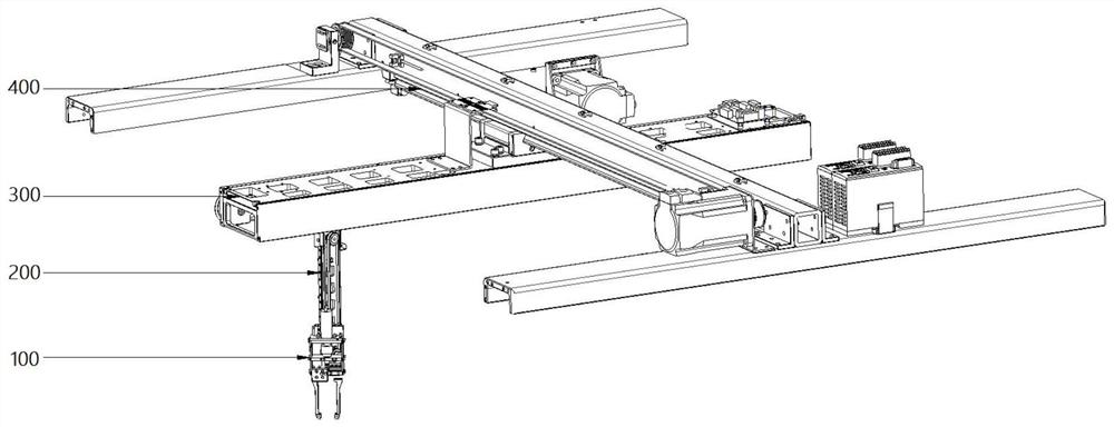
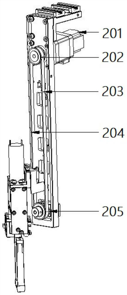
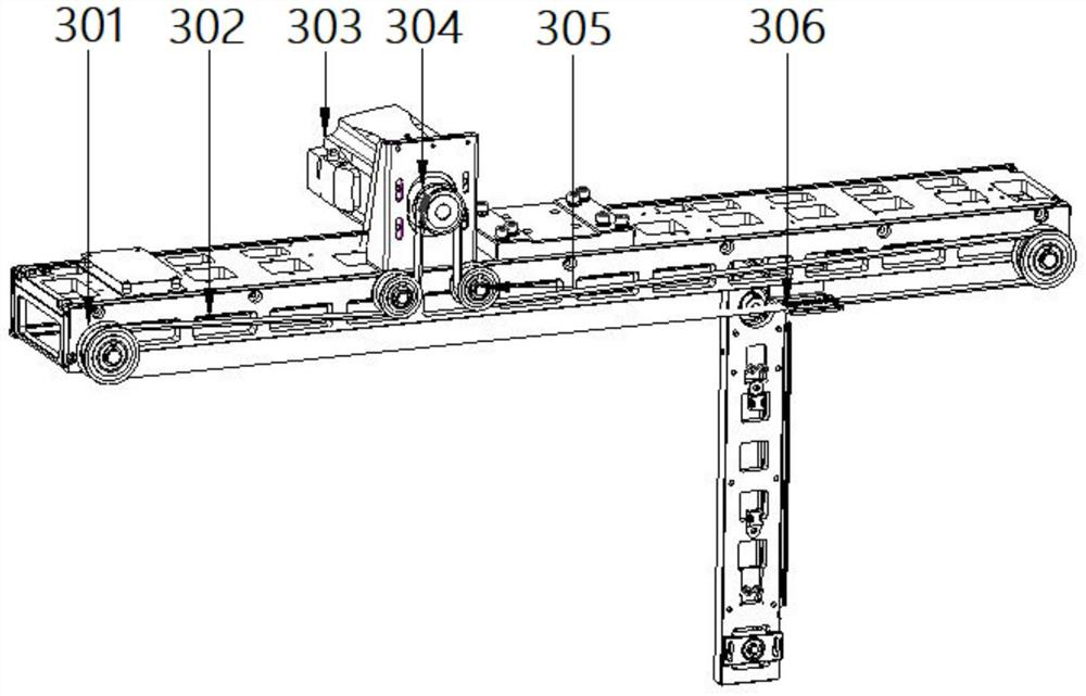
[0049] Such as Figure 1-Figure 6 As shown, the embodiment of the present invention provides a test tube placement system, including a test tube grasping device 100, a first driving mechanism 200 for driving the test tube grasping device 100 to move along a first direction, and a first driving mechanism 200 for driving the test tube grasping device 1...


PUM


Abstract

The invention discloses a test tube placing system, comprising: a test tube gripping device, the test tube gripping device comprises a test tube gripping support, a driving device, a limiting mechanism, a position sensing mechanism and two symmetrically arranged gripping pieces, and the gripping pieces are movably arranged relative to the test tube gripping support; a main body of the driving device is fixed relative to the test tube grabbing bracket; the driving device drives the grabbing hand pieces to get close to and get away from each other; the limiting mechanism is used for limiting the clamping force of the two gripper pieces after the test tube is clamped; the position sensing mechanism is used for detecting the distance between the two gripper pieces. The first driving mechanism is used for driving the test tube grabbing device to move in the first direction; the second driving mechanism is used for driving the test tube grabbing device to move in the second direction, and the second direction is perpendicular to the first direction; the third driving mechanism is used for driving the test tube grabbing device to move in the third direction, and the third direction is perpendicular to the first direction and the second direction. The labor intensity is reduced, the automation degree is improved, and the test tube placing efficiency is improved.

Description

technical field [0001] The invention relates to the technical field of test tube placement equipment, in particular to a test tube placement system. Background technique [0002] At present, the current hospital sample test tubes are usually inserted into the round holes of the test tube racks distributed equidistantly. Such a regular layout is conducive to the implementation of automation, improving work efficiency and reducing labor costs. However, due to the short space distance of the test tubes in the test tube rack, the test tubes are densely placed and the travel distance is long, and the grasping, storage and classification of the test tubes require high positioning accuracy, which is not convenient for automatic implementation. Moreover, since the thickness and length of the test tubes used in the hospital sample test tubes are different according to the test items, the length and thickness of the test tubes used can be distinguished with the naked eye during manual...

Claims


Application Information

Patent Timeline
Patent Type & Authority Applications(China)
IPC IPC(8): B07C5/06B07C5/12B07C5/36B25J15/00B25J19/02
CPCB07C5/06B07C5/122B07C5/362B25J15/00B25J15/0038B25J19/02
Inventor 侯剑平赵鹏徐灿徐振亚雷亚飞许振营王超刘聪
Owner AUTOBIO LABTEC INSTR CO LTD
Why Eureka
Try Eureka