Clamping mechanism for industrial robot

An industrial robot and clamping mechanism technology, applied in the direction of chucks, manipulators, manufacturing tools, etc., can solve the problems of difficult operation, troublesome maintenance, and complex structure of the clamping mechanism, and achieve simple structure of the clamping mechanism, easy operation and The effect of using

Inactive Publication Date: 2019-06-25
合肥伟达智能科技有限公司
View PDF5 Cites 7 Cited by
  • Summary
  • Abstract
  • Description
  • Claims
  • Application Information

AI Technical Summary

Problems solved by technology

Its task is to assist or replace human work, such as production, construction, or dangerous work. With the continuous advancement of science and technology and the continuous development of robotics, robots are gradually accepted by the public. Robots are used in industrial processing. It is convenient and widely used. The clamping mechanism is one of the important parts of the robot. The structure of the clamping mechanism of the existing industrial robot is too complicated, which is not only difficult to operate, but also very troublesome to maintain.

Method used


Image

  • Clamping mechanism for industrial robot
  • Clamping mechanism for industrial robot
  • Clamping mechanism for industrial robot

Examples


Embodiment Construction

[0027] The technical solutions of the present invention will be clearly and completely described below in conjunction with the embodiments. Apparently, the described embodiments are only some of the embodiments of the present invention, not all of them. Based on the embodiments of the present invention, all other embodiments obtained by persons of ordinary skill in the art without creative efforts fall within the protection scope of the present invention.

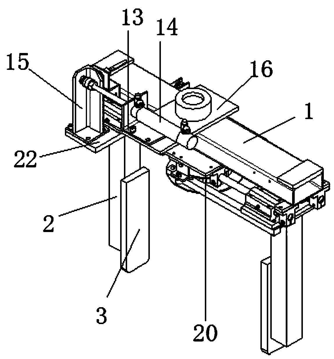
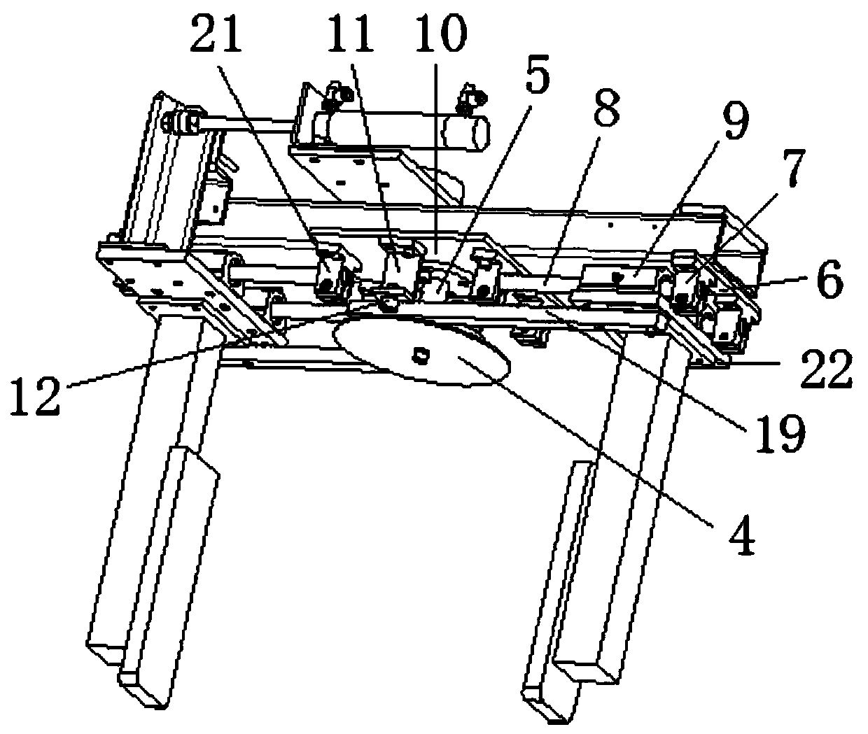
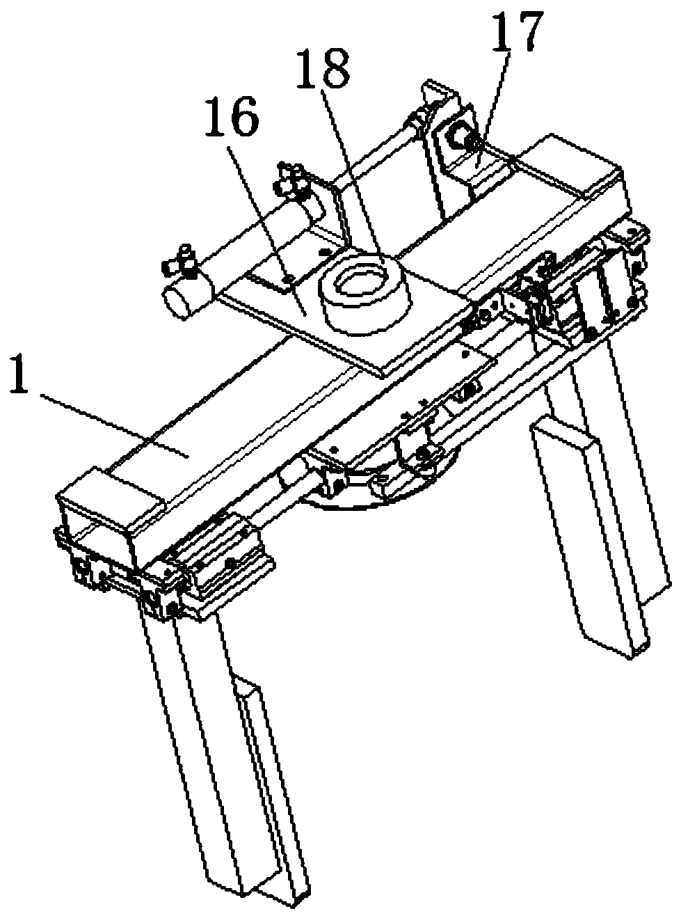
[0028] Such as Figure 1-4 As shown, a clamping mechanism for an industrial robot includes a mounting cross bar 1, a moving clamping rod 2, a clamping plate 3 and a drive cylinder 14. The bottom surface of the mounting cross bar 1 is fixed with two fixed bolts. Latches 6, and two said fixed laths 6 are symmetrically arranged at the bottom surface of both sides of the mounting bar 1, the bottom surface of said fixed laths 6 is fixed with two first mounts 7 by bolts, and the two The first mounting seat 7 is symmetrically arr...


PUM


Abstract

The invention discloses a clamping mechanism for an industrial robot. The clamping mechanism comprises a mounting cross rod, movable clamping rods, clamping plates and a driving air cylinder. The driving air cylinder is started to drive a movable bottom plate on one side to move through a first fixed plate, the movable bottom plate drives a straight gear to rotate through one guide rod, therefore,a movable bottom plate on the other side is driven to move through the other guide rod, and the two movable clamping rods drive the clamping plates to move oppositely or reversely for clamping or loosening. The clamping mechanism is simple in structure and convenient to operate and use; two moving bases are arranged on the movable bottom plates and slide on fixed sliding rods, so that stable movement of the movable bottom plates and the movable clamping rods is guaranteed, and the clamping effect of the clamping plates is guaranteed. A connecting lug is arranged on a sliding block, a spring is arranged between the connecting lug and a second fixing plate, so that the movable clamping rods provide buffering in the moving process, the movable clamping rods are prevented from colliding witha circular baffle during clamping, and the safety performance is high.

Description

technical field [0001] The invention relates to the technical field of industrial machinery and equipment, in particular to a clamping mechanism for industrial robots. Background technique [0002] A robot is a machine device that performs work automatically. It can accept human command, run pre-programmed programs, and act according to principles formulated with artificial intelligence technology. Its task is to assist or replace human work, such as production, construction, or dangerous work. With the continuous advancement of science and technology and the continuous development of robotics, robots are gradually accepted by the public. Robots are used in industrial processing. It is convenient and widely used. The clamping mechanism is one of the important parts of the robot. The structure of the clamping mechanism of the existing industrial robot is too complicated, which is not only difficult to operate, but also very troublesome to maintain. Contents of the inventio...

Claims


Application Information

Patent Timeline
Patent Type & Authority Applications(China)
IPC IPC(8): B25J15/02
Inventor 巩伟丁文明巩杰
Owner 合肥伟达智能科技有限公司
Why Eureka
Try Eureka