Dual-drive multi-knuckle bionic gripper

A dual-drive and gripper technology, applied in the field of robots, can solve the problems of increasing time and production costs, unable to meet the problems of fragile grasping, low reliability, etc., to achieve a simplified structure, facilitate human-machine collaboration, and ensure the clamping effect. Effect

Pending Publication Date: 2020-04-24
ZHEJIANG SCI-TECH UNIV
View PDF0 Cites 7 Cited by
  • Summary
  • Abstract
  • Description
  • Claims
  • Application Information

AI Technical Summary

Problems solved by technology

[0002] Existing grippers are mainly divided into rigid linkage mechanism and flexible bionic mechanism. Among them, the end of the rigid linkage mechanism is mostly metal fixtures, which cannot meet the needs of grasping fragile objects or objects that require special protection on the surface; while the flexible bionic mechanism is in the The structure is simpler than the rigid link mechanism, and the damage to the surface of the target object is less, but the flexible bionic mechanism needs a special gripper for the task of grabbing new parts, and some grippers made of special materials are relatively expensive. Increased time and production costs; at the same time, there are too many drives in the mechanical structure of the existing gripper, and the reliability is not high

Method used


Image

  • Dual-drive multi-knuckle bionic gripper
  • Dual-drive multi-knuckle bionic gripper
  • Dual-drive multi-knuckle bionic gripper

Examples


Embodiment Construction

[0026] The present invention will be further described below in conjunction with the accompanying drawings, but the present invention is not limited to the following examples.

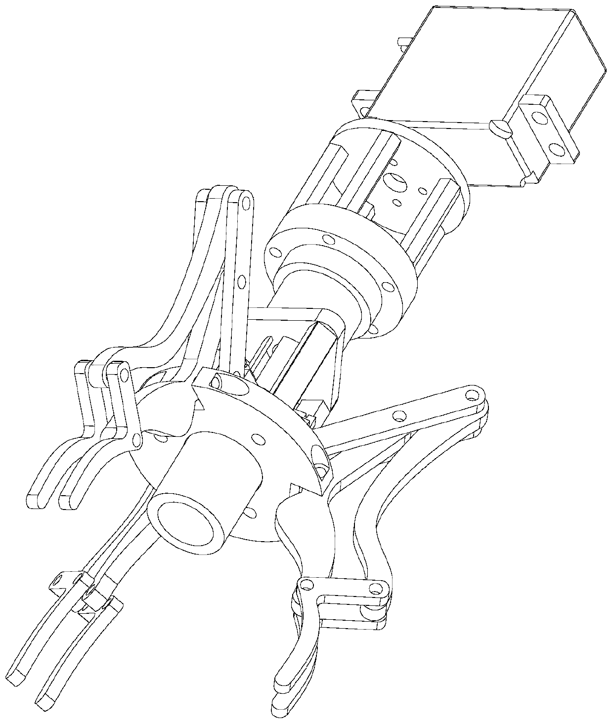
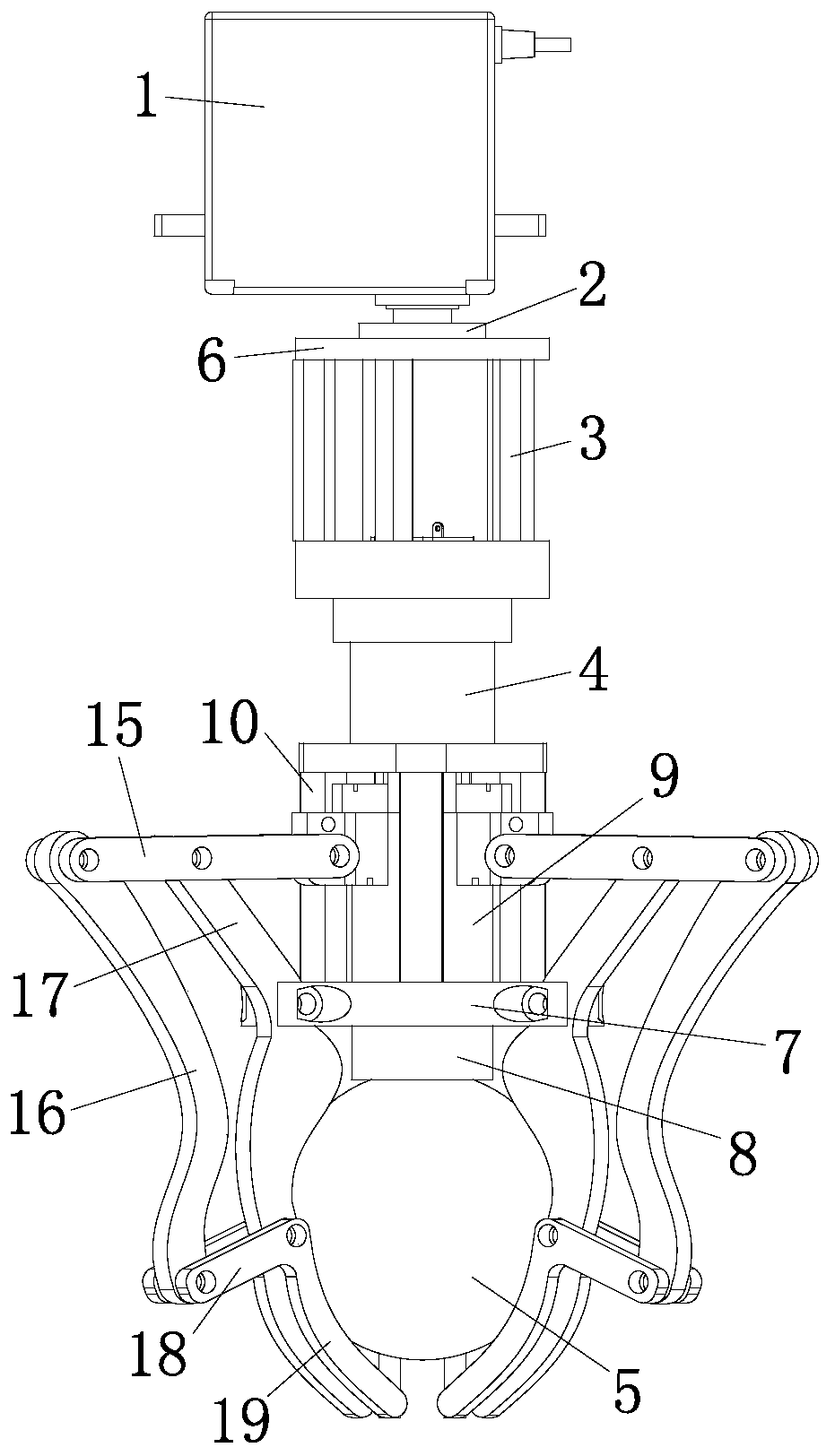
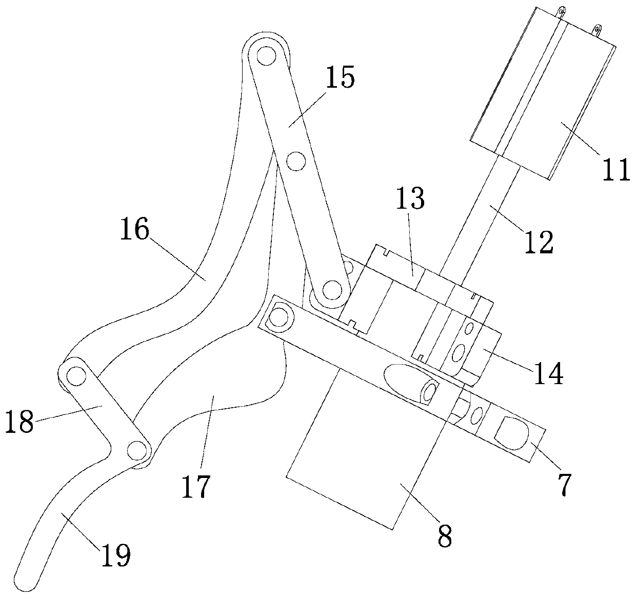
[0027] Such as figure 1 As shown, the dual-drive multi-knuckle bionic gripper includes a frame, a first motor 1, a second motor 11, a support platform 8, gripper branches and a transmission mechanism. The first motor is arranged at the rear end of the rack ( figure 2 The upper part of the middle frame), the first motor is used to drive the frame to rotate around the axis, the second motor is arranged in the frame, and the pallet is telescopically positioned at the front end of the frame ( figure 2 The lower part of the middle frame), several gripper branches are also arranged at the front end of the frame and evenly arranged around the pallet, and the transmission mechanism is used to transmit the second motor power to drive the pallet and the gripper branch to move. Three gripper branches are even...


PUM


Abstract

The invention relates to the field of robots, and aims to provide a dual-drive multi-knuckle bionic gripper. The device can integrate the advantages of a rigid connecting rod mechanism and a flexiblebionic mechanism, and has the characteristics of simple structure and high reliability. The technical scheme is as follows: the dual-drive multi-knuckle bionic gripper is characterized by comprising:a rack, a first motor used for driving the rack to rotate around the axis, a second motor arranged in the rack, a supporting table which is telescopically positioned at the front end of the rack, gripper branches arranged on the periphery of the supporting table, and a transmission mechanism used for transmitting power of the second motor to drive the supporting table and the gripper branches to move. The transmission mechanism comprises: a guide rails arranged in the rack and parallel to the length direction of the rack, a push plate capable of sliding along the guide rails, a lead screw driven by the second motor, and a nut meshed with the lead screw and fixed on the push plate. The supporting table is slidably positioned on the guide rails, a plurality of connecting blocks are arrangedon the supporting table, and the connecting blocks are connected to the push plate through elastic bodies.

Description

technical field [0001] The invention relates to the field of robots, in particular to a double-drive multi-knuckle bionic gripper used for the end effector of a robot. Background technique [0002] Existing grippers are mainly divided into rigid linkage mechanism and flexible bionic mechanism. Among them, the end of the rigid linkage mechanism is mostly metal fixtures, which cannot meet the needs of grasping fragile objects or objects that require special protection on the surface; while the flexible bionic mechanism is in the The structure is simpler than the rigid link mechanism, and the damage to the surface of the target object is less, but the flexible bionic mechanism needs a special gripper for the task of grabbing new parts, and some grippers made of special materials are relatively expensive. Increased time and production costs; at the same time, the mechanical structure of the existing gripper is driven too much, and the reliability is not high. Contents of the i...

Claims


Application Information

Patent Timeline
Patent Type & Authority Applications(China)
IPC IPC(8): B25J15/00B25J15/10B25J15/02
CPCB25J15/0009B25J15/0206B25J15/10
Inventor 马锃宏杜小强王朋成陆文武杜凡邢文松
Owner ZHEJIANG SCI-TECH UNIV
Why Eureka
Try Eureka