

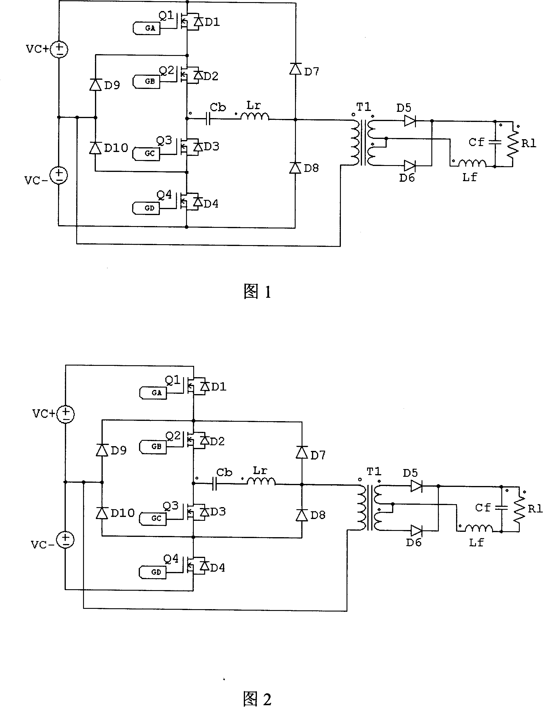
Original edge clamp circuit of DC converter
A technology of DC converter and clamping circuit, which is applied in the direction of converting DC power input to DC power output, intermediate conversion to AC conversion equipment, conversion of AC power input to DC power output, etc., which can solve the problem of switch tube damage and transformer T1 bias magnetic saturation and other issues
- Summary
- Abstract
- Description
- Claims
- Application Information
AI Technical Summary
Problems solved by technology
Method used
Image

Examples
Embodiment 1
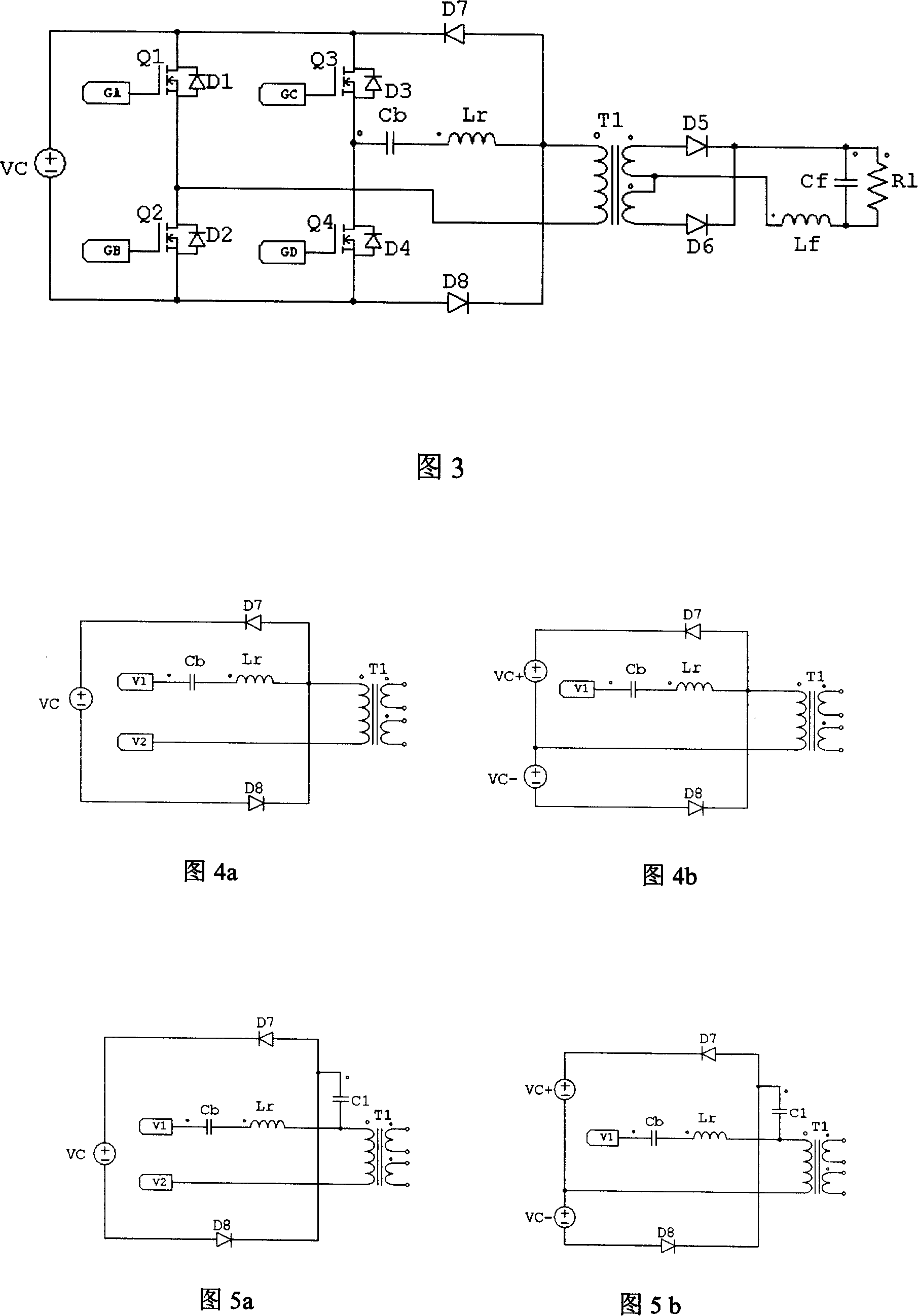
[0038] Embodiment 1 (first form):
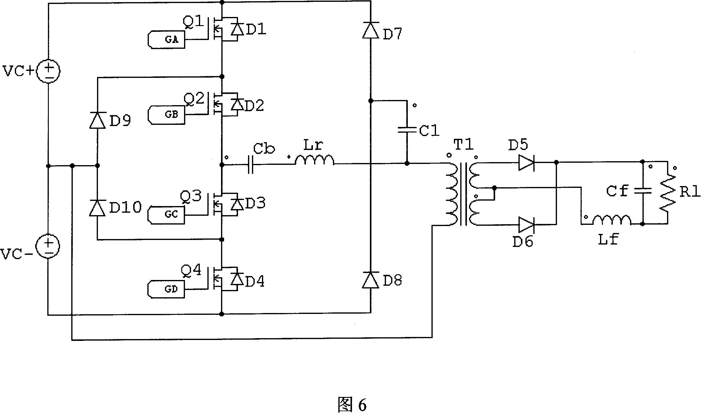
[0039] After analysis, we found that as long as some improvements are made to the clamping circuit topology (as shown in Figure 4) in Figure 1, Figure 2 and Figure 3, that is, the clamped point between the resonant inductor Lr and the transformer T1 is connected to the diodes D7 and D8 Add a capacitor C1 between the connection lines (as shown in Figure 5). The selection of capacitor C1 parameters will have a certain impact on the performance of the circuit. When the capacitance of C1 is too large, the DC blocking capacitor Cb can still form a discharge channel through C1; when the value of capacitor C1 is too small, it will directly affect the clamping circuit. Clamping effect on the voltage across the transformer and the secondary diode. The value of capacitor C1 generally needs to meet Cb / 25<C1<Cb / 8. In a circuit with attenuation resistor R2, the capacitor value C1 and resistor value R2 also need to satisfy R2*C1<T / 2, where T is the conve...
PUM
 Abstract
Description
Claims
Application Information