Phase shift full bridge converter with reduced current stress

a converter and current stress technology, applied in the direction of electric variable regulation, process and machine control, instruments, etc., can solve the problems of occupying a large volume, reducing total efficiency, increasing power consumption, etc., and achieves the effect of reducing current stress, reducing current stress, and reducing current stress

Active Publication Date: 2010-01-07
SOLUM CO LTD
View PDF7 Cites 15 Cited by
  • Summary
  • Abstract
  • Description
  • Claims
  • Application Information

AI Technical Summary

Benefits of technology

[0011]An advantage of the present invention is that it provides a phase shift full bridge converter which is capable of reducing current stress by removing an output inductor and adding an auxiliary circuit unit to a secondary side of a transformer.
[0012]Additional aspects and advantages of the present general inventive concept will be set forth in part in the description which follows and, in part, will be obvious from the description, or may be learned by practice of the general inventive concept.
[0013]According to an aspect of the invention, a phase shift full bridge converter with a reduced current stress includes: a switching unit that switches an input voltage; a transformer that includes a first capacitor serially connected to, and having a primary side and a secondary side; an auxiliary circuit unit that includes a first switch, a second switch, and a second capacitor, which are connected in parallel to the secondary side of the transformer; and a rectification unit that is connected to the auxiliary circuit unit, with an output inductor being removed.
[0014]The transformer may include a leakage inductor and reduce current stress by using a resonance between the leakage inductor and the first capacitor
[0015]The auxiliary circuit unit may include: a first switch; a second capacitor connected to the first switch; and a second switch connected to the second capacitor.
[0016]The auxiliary circuit unit may operate at the same time when a free wheeling interval of a synchronous rectifier is completed, and increase a secondary current of the transformer.

Problems solved by technology

In addition, for user's convenience, functions of processors increase and thus their power consumption also increase.
However, as the switching frequency increases, a total efficiency is reduced due to loss generated in the switching.
In addition, since an output inductor exists at a position where a high load current flows, it occupies a large volume.
Moreover, in magnetic devices, power loss is caused by core loss and conduction loss.
However, in this case, a leakage inductor of a transformer replaces the role of the output inductor.
Thus, since a secondary current operates as a discontinuous conduction mode, there is a problem that increases current stress of a synchronous rectifier of a secondary side in order to supply a high load current.

Method used


Image

  • Phase shift full bridge converter with reduced current stress
  • Phase shift full bridge converter with reduced current stress
  • Phase shift full bridge converter with reduced current stress

Examples


Embodiment Construction

[0023]Reference will now be made in detail to the embodiments of the present general concept, examples of which are illustrated in the accompanying drawings, wherein like reference numerals refer to like elements throughout. The embodiments are described below in order to explain the present general inventive concept by referring to the figures. In the drawings, the thicknesses of layers and regions are exaggerated for clarity.

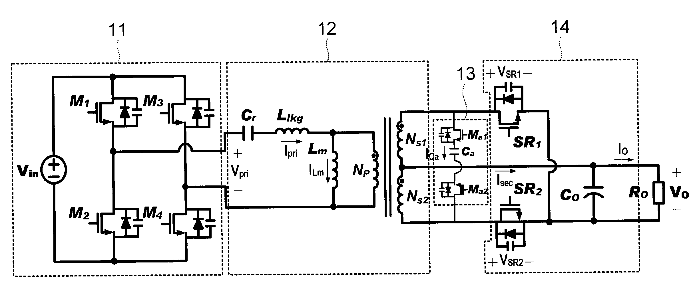
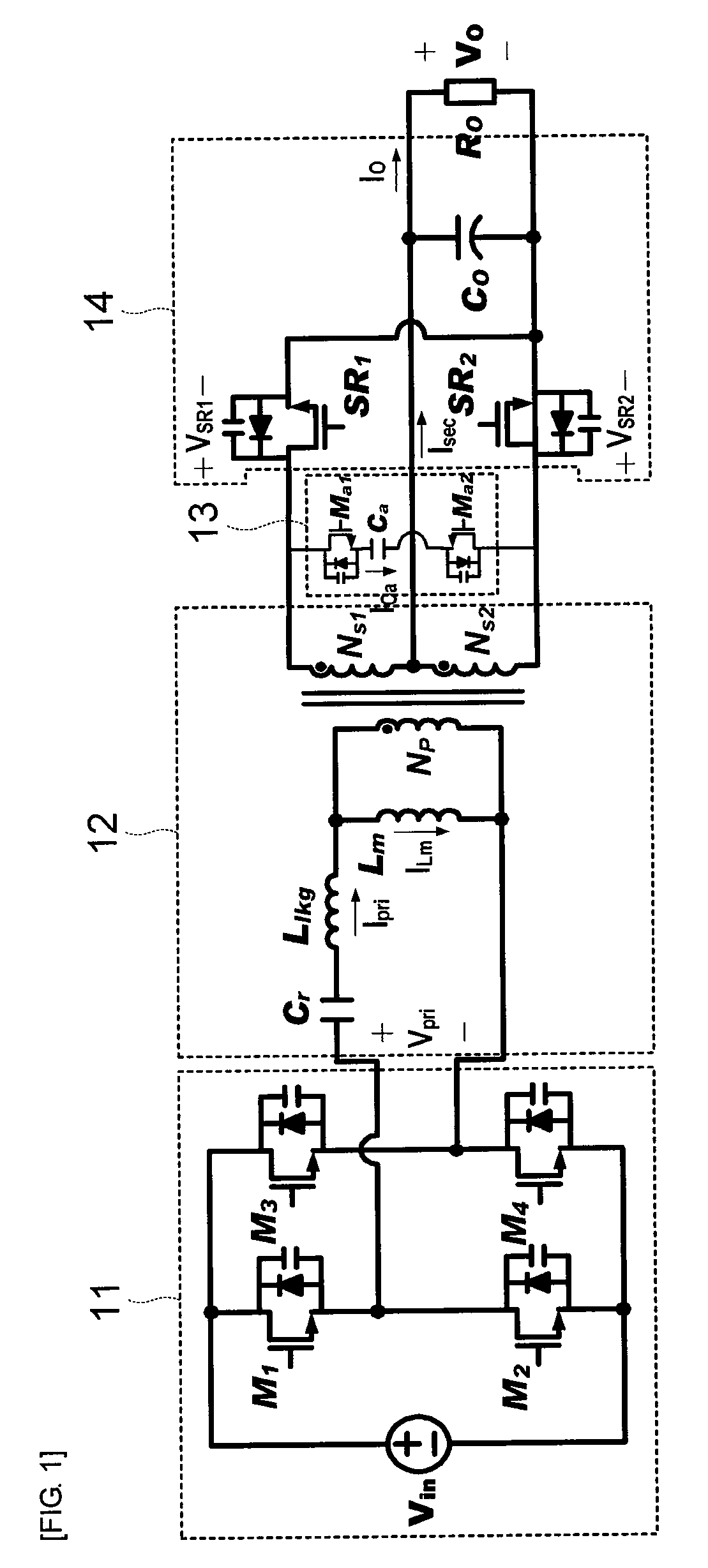
[0024]FIG. 1 is a circuit diagram of a phase shift full bridge converter with reduced current stress according to the present invention.

[0025]Referring to FIG. 1, the phase shift full bridge converter includes a switching unit 11, a transformer 12, an auxiliary circuit unit 13, and a rectification unit 14.

[0026]The switching unit 11 switches an input voltage through four switches having a full bridge configuration.

[0027]The transformer 12 includes a first capacitor Cr serially connected thereto, and has a primary side and a secondary side. In addition, the tra...


PUM


Abstract

A phase shift full bridge converter with a reduced current stress includes: a switching unit that switches an input voltage; a transformer that includes a first capacitor serially connected to, and having a primary side and a secondary side; an auxiliary circuit unit that includes a first switch, a second switch, and a second capacitor, which are connected in parallel to the secondary side of the transformer; and a rectification unit that is connected to the auxiliary circuit unit, with an output inductor being removed.

Description

CROSS-REFERENCE TO RELATED APPLICATIONS[0001]This application claims the benefit of Korean Patent Application No. 10-2008-0064892 filed with the Korean Industrial Property Office on Jul. 4, 2008, the disclosure of which is incorporated herein by reference.BACKGROUND OF THE INVENTION[0002]1. Field of the Invention[0003]The present invention relates to a phase shift full bridge converter, and more particularly, to a phase shift full bridge converter which is capable of reducing current stress by removing an output inductor and adding an auxiliary circuit unit to a secondary side of a transformer.[0004]2. Description of the Related Art[0005]Recently, a power supply circuit supplies power from a general-use input line (85 Vac˜265 Vac) through a power factor correction circuit to a DC / DC voltage terminal, and the power is transformed into a desired power at the DC / DC voltage terminal.[0006]The power factor correction circuit is used in order to meet harmonics regulation that is recently ...

Claims


Application Information

Patent Timeline
Patent Type & Authority Applications(United States)
IPC IPC(8): H02M3/335
CPCH02M3/33592H02M3/337Y02B70/1475H02M2007/53878Y02B70/1441H02M2007/4818Y02B70/10H02M7/4818H02M7/53878H02M3/33573H02M3/01H02M7/48H02M7/5387
Inventor HEO, TAE WONMOON, GUN WOOLEE, WOO JINPARK, KI BUMKIM, DON SIKKIM, CHONG EUNKIM, JONG PILBONG, SANG CHEOLKIM, HAK RYONGKIM, DONG JOONG
Owner SOLUM CO LTD
Why Eureka
Try Eureka