
Full bridge converter with zero voltage and zero current

A zero-voltage, zero-current, DC-DC technology, applied in high-efficiency power electronic conversion, conversion of DC power input to DC power output, adjustment of electrical variables, etc., can solve the loss of duty cycle, increase circuit on-state loss, saturated inductance The problem of difficult selection of magnetic materials, etc., achieves the effect of simple structure and reliable operation

Inactive Publication Date: 2009-01-28
JIANGSU UNIV
View PDF0 Cites 16 Cited by
  • Summary
  • Abstract
  • Description
  • Claims
  • Application Information

AI Technical Summary

Problems solved by technology

The disadvantages of the circuit structure of these two full-bridge DC / DC converters are: 1. Due to the existence of the saturated inductance Ls in the main switch circuit, not only the loss of the duty cycle is caused, but also the design of the saturated inductance and the selection of magnetic materials are more difficult ; 2. The diode D connected in series with the lagging bridge arm 2 、D 4 Increase the on-state loss of the circuit, thus limiting the improvement of the maximum efficiency of the circuit

Method used


Image

  • Full bridge converter with zero voltage and zero current
  • Full bridge converter with zero voltage and zero current
  • Full bridge converter with zero voltage and zero current

Examples


Embodiment Construction

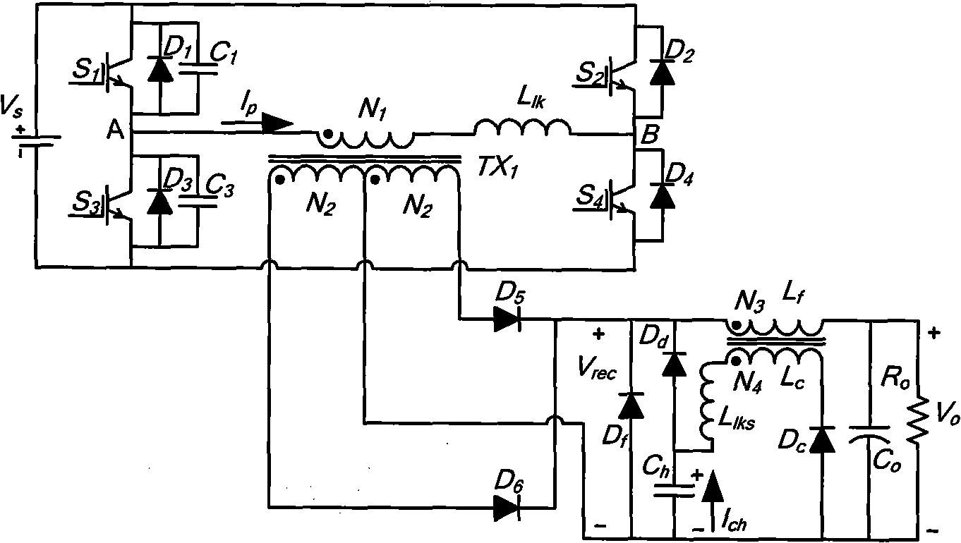
[0011] Such as image 3 As shown, the main circuit includes four power transistors S 1 , S 3 , S 2 , S 4 , nine diodes D1 ~ D6, D d 、D f 、D C , three capacitors C 1 、C 3 and Ch, transformer TX 1 , a full-bridge PWM converter composed of filter inductor Lf and power supply Vs. In the super forearm switch tube S 1 , S 3) and the lagging arm switch S 2 , S 4 Both ends of the anti-parallel diode D 1 、D 3 、D 2 、D 4 , and then in the super forearm switch S 1 , S 3 Upper parallel capacitor C 1 、C 3 ; in transformer TX 1 The end with the same name on the primary side is connected to the switch tube S 1 on the transmitter side of the transformer TX 1 The non-identical end of the primary side is connected to the inductor Llk; in the transformer TX 1 The terminal with the same name on the secondary side is connected to the diode D 6 The positive pole of the secondary side is connected to the diode D with the non-identical end of the secondary side 5 positive pol...


PUM


Abstract

The present invention discloses a zero voltage zero current full-bridge DC-DC converter. Diodes are respectively and reversely connected in parallel with two ends of lead arm switching tubes and lagging switching tubes. Capacitors C1,C3 are connected in parallel with the lead arm switching tubes S1,S3. A homonymous terminal at the primary side of a transformer TX1 is connected to a transmitting terminal of the lead arm switching tube S1. A synonymous terminal at the primary side of the transformer TX1 is connected to an inductor LIK. A homonymous terminal of the secondary side of the transformer is connected to the anode of a diode D6, while a synonymous terminal of the secondary side is connected to the anode of a diode D5. An output coupling inductive circuit is added to the cathodes of the diodes D5,D5 and two ends of the center of the secondary side of the transformer. The output coupling inductive circuit mainly consists of a clamp capacitor Ch, an output coupling inductor Lc, and diodes Df,Dd,Dc. The converter can realize zero voltage zero current soft switching at a wider load range. Auxiliary circuits have no dissipative elements. The inductor does not need to store energy in advance. The stress of the current at the primary side is not increased.

Description

technical field [0001] The invention relates to a DC / DC (direct current / direct current) power conversion device, in particular to a PWM (pulse width modulation) full-bridge converter which utilizes an output coupling inductance to realize zero-voltage and zero-current switching. Background technique [0002] At present, the zero-voltage and zero-current soft-switching full-bridge DC / DC converter circuit is a soft-switching technology for the main switching circuit. There are two commonly used circuit structures. One is as follows: figure 1 As shown in the full bridge structure, the super forearm switch S 1 , S 3 and the lagging arm switch S 2 , S 4 Both ends of the anti-parallel diode D 1 、D 3 、D 2 、D 4 , then in D 1 、D 3 on the shunt capacitor, C 1 、C 3 . In Transformer TX 1 The end with the same name on the primary side is connected to C b end of the C b The other end of the connection S 1 on the transmitter side of the transformer TX 1 The non-identical e...

Claims


Application Information

Patent Timeline
Patent Type & Authority Applications(China)
IPC IPC(8): H02M3/335H02M3/07
CPCY02B70/1491Y02B70/10
Inventor 刘星桥陈光菊
Owner JIANGSU UNIV
Learn More