Fire-fighting unmanned aerial vehicle
A drone and fire-fighting technology, applied in the field of drones, can solve problems such as uncontrollable drones, cluttered air flow, and impact of drone airflow
- Summary
- Abstract
- Description
- Claims
- Application Information
AI Technical Summary
Problems solved by technology
Method used
Image

Examples
Embodiment Construction
[0026] The following will clearly and completely describe the technical solutions in the embodiments of the present invention with reference to the accompanying drawings in the embodiments of the present invention. Obviously, the described embodiments are only some, not all, embodiments of the present invention. Based on the embodiments of the present invention, all other embodiments obtained by persons of ordinary skill in the art without making creative efforts belong to the protection scope of the present invention.
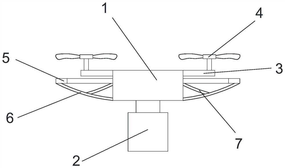
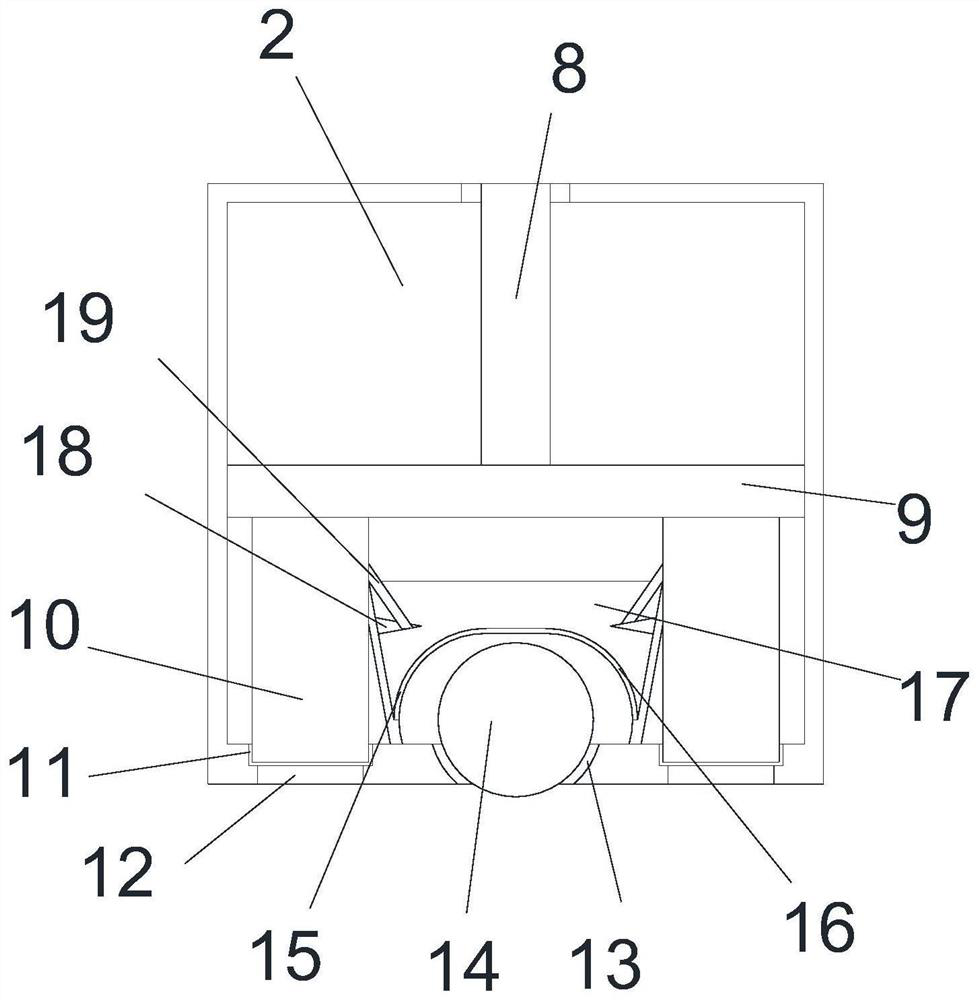
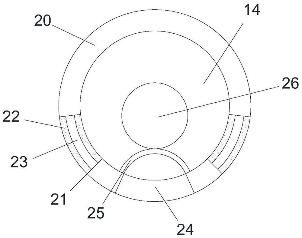
[0027] see Figure 1-Figure 6 , the present invention provides a technical solution: a fire-fighting unmanned aerial vehicle, comprising an equipment box 1, a control device and a driving device are arranged inside the equipment box 1, a fire box 2 is fixedly installed on the bottom of the equipment box 1, and the fire box 2 The interior is hollow, and the side wall of the equipment box 1 is fixed with a driving rod 3 in a ring shape. The top end of the drivin...
PUM
 Abstract
Description
Claims
Application Information
PatSnap Eureka turns technology decisions into work you can execute. Powered by our Innovation Knowledge Graph, it runs expert workflows across engineering, life sciences, materials and intellectual property. Get your review-ready output in minutes.


