
Automatic plate feeding device

A sheet and push plate technology, applied in the field of automatic sheet feeding devices, can solve the problems of low efficiency and imprecise grasping target, and achieve the effect of avoiding sheet bonding

Inactive Publication Date: 2021-04-20
CHONGQING IND POLYTECHNIC COLLEGE
View PDF10 Cites 1 Cited by
  • Summary
  • Abstract
  • Description
  • Claims
  • Application Information

AI Technical Summary

Problems solved by technology

[0005] The purpose of the present invention is to overcome the problems of low efficiency and inaccurate grasping targets of the above-mentioned board feeding device, and provide an automatic board feeding device

Method used


Image

  • Automatic plate feeding device
  • Automatic plate feeding device

Examples


Embodiment

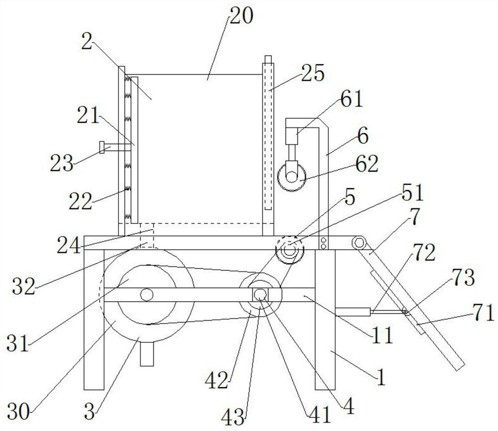
[0028] Such as Figure 1~2 As shown, an automatic sheet material feeding device includes a frame 1, the upper surface of the frame 1 is provided with a storage bin 2; the bottom of the frame 1 is provided with a pushing mechanism 3 and a driving mechanism 4 through a beam 11; The frame 1 is formed into a three-dimensional structure by splicing several brackets;

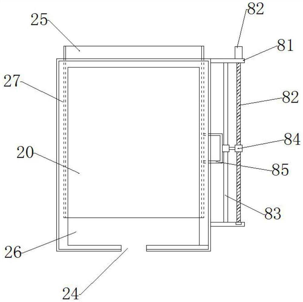
[0029] The storage bin 2 includes a box body 20, the box body 20 is set as a hollow structure with an upper opening, and a push groove 24 is arranged in a horizontal hollow in the middle of the bottom of the box body 20; the bottom of the box 20;

[0030] The right side of the box body 20 is provided with an opening 26, and the two sides of the opening 26 are provided with slots 27, and the slots 27 are set to two and oppositely arranged, and the notches of the two slots 27 are opposite to each other. To set, two slots 27 are inserted into the baffle plate 25 from the vertical direction, for partially closing the op...


PUM


Abstract

The invention discloses an automatic plate feeding device. The feeding device comprises a rack, and a storage bin is arranged on the upper surface of the rack; a pushing mechanism and a driving mechanism are arranged at the bottom of the rack through a cross beam; the storage bin comprises a box body, the box body is of a hollow structure with an opening at the upper portion, and a pushing groove is transversely formed in the middle of the bottom of the box body in a hollowed-out manner; and an opening is formed in the right side face of the box body, inserting grooves are formed at the two sides of the opening, and baffles are vertically inserted into the inserting grooves and used for partially sealing the opening. The device is simple in process and capable of rapidly providing corresponding plate raw materials for a production line. By improving the adaptive structure of the storage bin and the pushing mechanism, the purpose of feeding single plates is achieved, and the situation that the plates are bonded is avoided. Due to adjustable pushing, the feeding speed and rhythm can be controlled. Requirements of different production lines are met.

Description

technical field [0001] The invention relates to the technical field of automatic machinery, in particular to an automatic plate feeding device. Background technique [0002] The boards that are stacked together need to be placed on the conveyor line one by one and sent backwards for subsequent processing. For example, when a flooring factory produces composite floors, the boards that are stacked together need to be put on the conveyor line in turn and sent backwards. Manually put the floors to be laminated one by one on the conveyor line for subsequent processing. [0003] The existing solution is to install an automatic grabbing device at the front or side of the conveyor line. The grabbing device lifts the plate to a certain height through a suction cup or a manipulator and then moves it to a designated position along the guide rail. The plate is placed on the conveyor line, and the plate is conveyed along the The line moves backwards, and the gripper resets to prepare to...

Claims


Application Information

Patent Timeline
IPC IPC(8): B65G65/40B65G69/00
Inventor 毛臣健
Owner CHONGQING IND POLYTECHNIC COLLEGE
Learn More