A rotary electrolysis device

An electrolysis device and rotary technology, applied in electrolysis components, electrolysis process, etc., can solve problems such as inability to realize continuous electrolysis, achieve the effect of improving automation and production efficiency, improving effect, and preventing air bubbles

Active Publication Date: 2021-11-30
无锡市鹏振智能科技有限公司
View PDF2 Cites 0 Cited by
  • Summary
  • Abstract
  • Description
  • Claims
  • Application Information

AI Technical Summary

Problems solved by technology

[0007] The purpose of the present invention is to disclose a rotary electrolysis device, which is used to solve the defect that continuous electrolysis cannot be realized in the electrolysis equipment in the technology, and to prevent the operator from contacting the electrolyte to improve safety

Method used


Image

  • A rotary electrolysis device
  • A rotary electrolysis device
  • A rotary electrolysis device

Examples


Embodiment 1

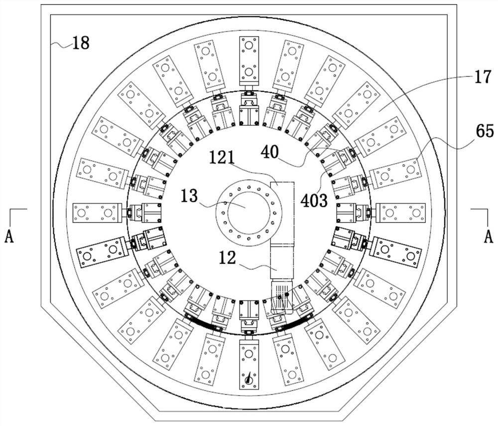
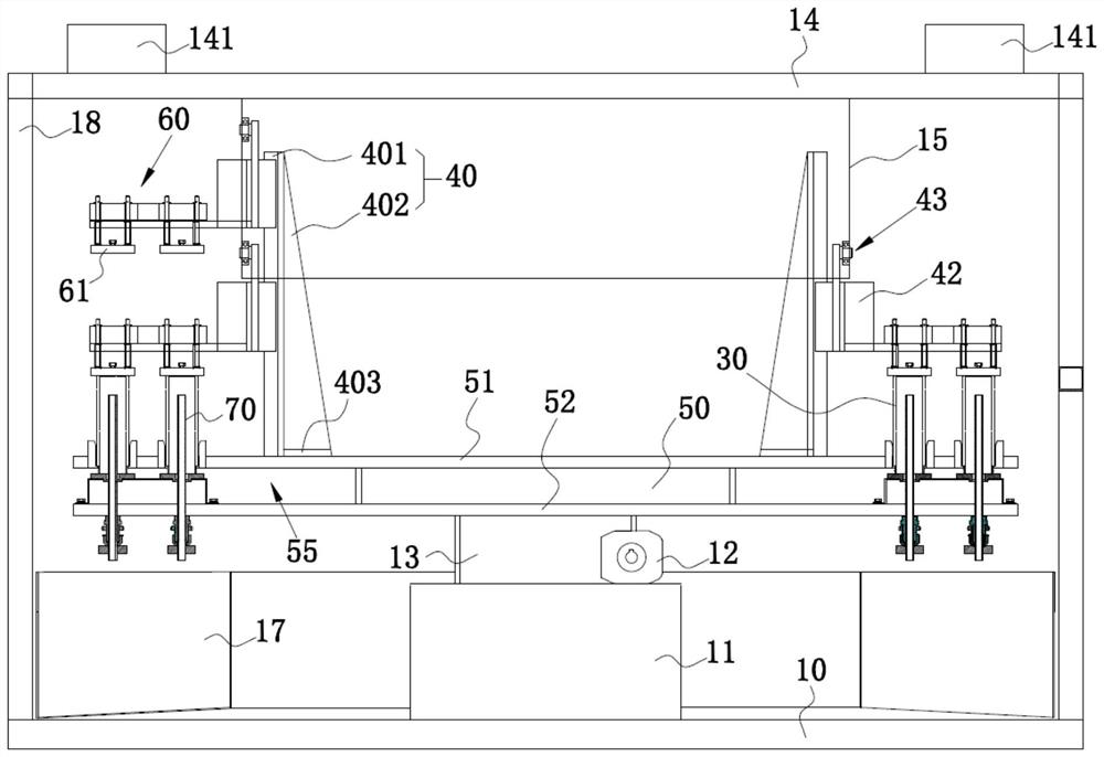
[0053] ginseng Figure 1 to Figure 4 As shown, this embodiment discloses a rotary electrolytic device (hereinafter referred to as "device"), which is used for electropolishing the cup body 30 with the opening downward, especially for electropolishing the inner wall surface of the cup body 30 .

[0054] In this embodiment, the device includes:

[0055] The driving mechanism is the base driven and rotated by the driving mechanism. The radially outer side of the base is annularly embedded with several cups 30 with downward openings, and the liquid storage tank 17 is arranged under the base. The liquid storage tank 17 is used For storing the electrolyte; a plurality of guide mechanisms 40 arranged vertically on the base in a ring, slidingly connected with the guide mechanism 40 and arranged on the radially outer side of the guide mechanism 40 and arranged in a ring, a plurality of anode devices 60 arranged in a ring and arranged in a ring A plurality of electrolytic rods 70 inse...

Embodiment 2

[0089] ginseng Figure 14 to Figure 16 As shown, this embodiment discloses another modified embodiment of a rotary electrolysis device of the present invention.

[0090] The difference between the rotary electrolysis device disclosed in this embodiment and the rotary electrolysis device disclosed in Embodiment 1 is that in this embodiment, the device includes: a driving mechanism, a base that is driven and rotated by the driving mechanism, The liquid storage tank 17 arranged under the base, a number of guide mechanisms 40 arranged vertically on the base in a ring, slidingly connected with the guide mechanism 40 and arranged radially outside the guide mechanism 40 and arranged in a ring. An anode device 60, a plurality of electrolytic rods 70 inserted into the opening of the cup body are arranged in a ring and run through the base. The electrolytic rods 70 are hollow and have a cathode 209 at the bottom. The anode device 60 is configured with a sliding block 42 slidably connec...


PUM


Abstract

The invention provides a rotary electrolysis device, which is used for electropolishing the cup body with the opening downward, including a driving mechanism, a base driven and rotated by the driving mechanism, and the radial outer side of the base is annularly embedded with the opening facing downward. Several cups below, a number of guide mechanisms arranged vertically on the base in a ring, a plurality of anode devices that are slidably connected to the guide mechanism and arranged radially outside the guide mechanism and arranged in a ring, arranged in a ring and run through the base A plurality of electrolytic rods inserted into the opening of the cup body, the electrolytic rods have a hollow structure; the anode device is equipped with a sliding block that is slidably connected to the guide mechanism, and the sliding block moves up and down in the vertical direction in an active or passive manner to drive the anode device and the cup body longitudinal separation and contact. In the present invention, the unloading and loading operations of the cup body are realized sequentially only in the guide separation area, which solves the technical problem of the traditional electrolytic polishing equipment that the electrolytic polishing time is too short and continuous loading and unloading cannot be realized.

Description

technical field [0001] The invention relates to the technical field of electrolysis equipment for metal products, in particular to a rotary electrolysis device. Background technique [0002] Electropolishing is a method of finishing the surface of a metal workpiece. The method is to place the metal workpiece in an electrolytic polishing tank filled with electrolytic polishing liquid, and energize the electrolytic polishing liquid for electrolysis. As the electrolysis proceeds, a liquid film with high viscosity is formed on the surface of the metal workpiece. The thickness distribution of the liquid film on the uneven surface of the metal workpiece is uneven. The liquid film on the surface of the convex part is thin, while the liquid film on the surface of the rest Thick, so the resistance of the anode surface is not the same everywhere. The raised part of the metal workpiece has low resistance and high current density, which makes the raised part dissolve faster than the co...

Claims


Application Information

Patent Timeline
Patent Type & Authority Patents(China)
IPC IPC(8): C25F3/16C25F7/00
Inventor 徐春奇
Owner 无锡市鹏振智能科技有限公司
Why Eureka
Try Eureka