Continuous electrolytic polishing device and method of alloy substrate used for coated conductor

A technology for electropolishing and coating conductors, applied in the field of electropolishing, can solve the problems of destroying the cubic texture of the baseband, unsuitable for surface polishing of the alloy baseband for coating conductors, etc., and achieves good engineering practical value, low manufacturing cost and simple method. Effect

Inactive Publication Date: 2011-08-03
NORTHWEST INSTITUTE FOR NON-FERROUS METAL RESEARCH
View PDF9 Cites 10 Cited by
  • Summary
  • Abstract
  • Description
  • Claims
  • Application Information

AI Technical Summary

Problems solved by technology

[0003] In the current polishing technology, mechanical polishing is not suitable for the surface polishing of alloy substrates for coated conductors because it is easy to generate surface stress and destroy the cubic texture of the substrate.

Method used


Image

  • Continuous electrolytic polishing device and method of alloy substrate used for coated conductor
  • Continuous electrolytic polishing device and method of alloy substrate used for coated conductor
  • Continuous electrolytic polishing device and method of alloy substrate used for coated conductor

Examples


Embodiment 1

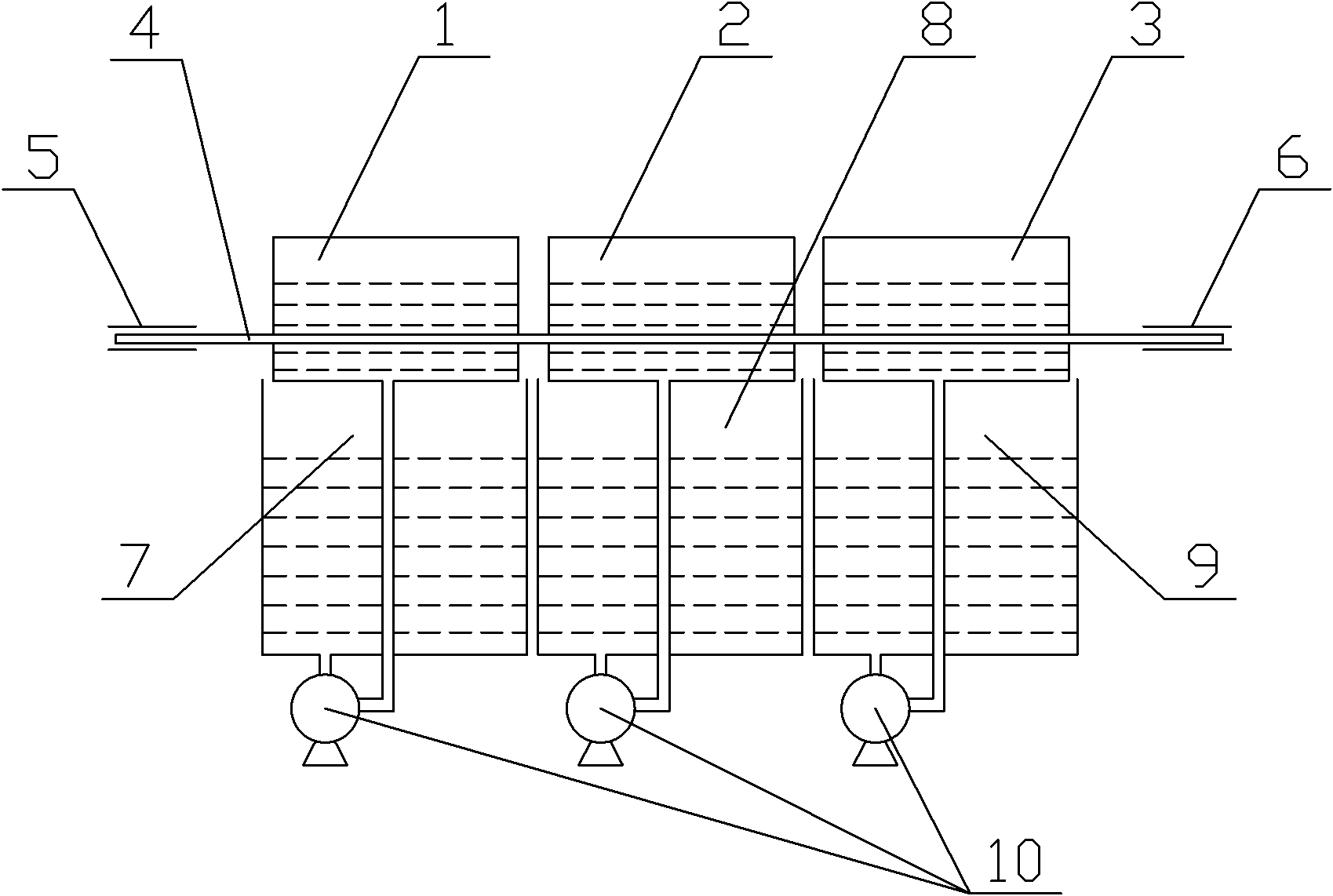
[0029] Step 1. Continuously wind the cleaned alloy base strip 4 on the tape reel 5, and then insert the outer end of the alloy base strip 4 from the left through hole of the anode tank 1 through the anode tank 1, After the inside of the electrolytic cell 2 and the anode cell 2 3, pull it out from the through hole on the right side of the anode cell 2 3 and wind it on the take-up reel 6;

[0030] Step 2: Add electrolyte solution in liquid storage tank 1 7, liquid storage tank 2 8 and liquid storage tank 3 9, and then turn on the circulation pump 10 to circulate the electrolyte into anode tank 1, electrolytic tank 2 and anode tank Two 3, and make the electrolytic solution in the anode tank one 1, the electrolytic tank 2 and the anode tank two 3 have not crossed the alloy substrate 4; Described electrolytic solution is that mass concentration is 65% sulfuric acid;

[0031] Step 3: Turn on the stepper motor, drive the alloy base tape 4 to move at a constant speed through the coope...

Embodiment 2

[0034] The method of this embodiment is the same as that of Embodiment 1, except that the current density of the electrolytic polishing is 80A / dm 2 , the electropolishing time of the alloy base strip 4 in the electrolytic bath 2 is 40s.

[0035] This embodiment can realize the continuous electrolytic polishing of the alloy base strip at the level of 100 meters, and the root mean square roughness of the electropolished alloy base strip in the range of 5 μm×5 μm is 3.5 nm.

Embodiment 3

[0037] The method of this embodiment is the same as that of Embodiment 1, except that the current density of the electrolytic polishing is 110A / dm 2 , the electropolishing time of the alloy base strip 4 in the electrolytic bath 2 is 20s.

[0038] This embodiment can realize the continuous electrolytic polishing of the alloy base strip at the level of 100 meters, and the root mean square roughness of the electropolished alloy base strip in the range of 5 μm×5 μm is 2.2 nm.


PUM

PropertyMeasurementUnit
surface roughnessaaaaaaaaaa

Abstract

The invention discloses a continuous electrolytic polishing device of alloy substrate used for coated conductor, which comprises a first anode tank, an electrolytic tank, a second anode tank, a substrate releasing disc, a substrate reeling disc as well as a first liquid storage box, a second liquid storage box and a third liquid storage box, wherein the first anode tank, the electrolytic tank and the second anode tank are sequentially arranged, and the left sides and the right sides of the first anode tank, the electrolytic tank and the second anode tank are all provided with through holes; the substrate releasing disc and the substrate reeling disc are used together with each other for continuously pulling the alloy substrate to be treated out of the inner parts of the first anode tank, the electrolytic tank and the second anode tank through the through holes after tightening the alloy substrate; and the first liquid storage box, the second liquid storage box and the third liquid storage box are respectively communicated with the first anode tank, the electrolytic tank and the second anode tank through circulating pumps. The invention also discloses a method for carrying out continuous electrolytic polishing on the alloy substrate used for coated conductor by using the device. The device has the advantages of simple structure, reasonable design and low manufacturing cost, and can realize continuous electrolytic polishing on hectometer-level alloy substrate. The root-mean-square roughness of the polished alloy substrate is less than 5nm by adopting the method for electrolytic polishing.

Description

technical field [0001] The invention belongs to the technical field of electrolytic polishing, and in particular relates to a continuous electrolytic polishing device and method for an alloy base strip for a coated conductor. Background technique [0002] The second-generation high-temperature superconducting tape, that is, the coated conductor, has aroused widespread interest in the material science community for its superior high-field performance at 77K. The coated conductor is a multilayer structure composed of alloy base strip / buffer layer / superconducting layer / protective layer. The alloy base strip is the coated conductor carrier. The main role in the superconducting strip is the epitaxial growth transition layer and superconducting layer. The surface quality of the baseband has an important influence on the performance of the epitaxial growth buffer layer and the superconducting layer; the coated conductor requires the surface roughness of the alloy baseband to be les...

Claims


Application Information

Patent Timeline
Patent Type & Authority Applications(China)
IPC IPC(8): C25F3/16C25F7/00
Inventor 李成山冀勇斌郑会玲王雪纪平
Owner NORTHWEST INSTITUTE FOR NON-FERROUS METAL RESEARCH
Why Eureka
Try Eureka