Welding method of curved-surface microstrip antenna

A technology of microstrip antenna and welding method, which is applied to antennas, welding equipment, welding equipment and other directions to achieve the effects of strong welding adaptability, reduced modification workload and good welding uniformity

Inactive Publication Date: 2020-11-20
10TH RES INST OF CETC
View PDF10 Cites 1 Cited by
  • Summary
  • Abstract
  • Description
  • Claims
  • Application Information

AI Technical Summary

Problems solved by technology

[0006] The purpose of the present invention is to address the deficiencies in the welding of existing curved surface microstrip antennas, to provide a welding method for curved surface microstrip antennas with strong welding adaptability, good welding uniformity, and high welding success rate, so as to meet the long-term requirements of curved surface microstrip antennas. Use reliability requirements

Method used


Image

  • Welding method of curved-surface microstrip antenna
  • Welding method of curved-surface microstrip antenna

Examples


Embodiment Construction

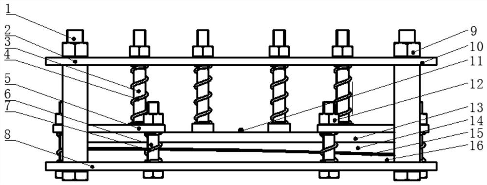
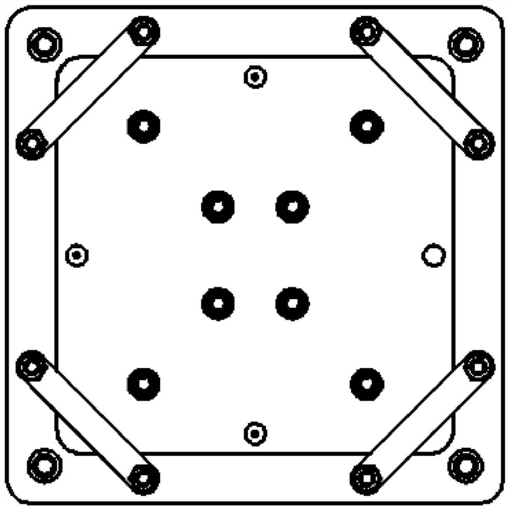
[0016] refer to figure 1 , figure 2 . According to the present invention, a clamping tool for clamping the microstrip 14 is prepared by using the curved surface shape of the microstrip antenna and the characteristics of the metal pattern, and a layer of solder is printed on the bottom of the microstrip 14 by stencil printing, and the flexible equalizing plate 13 Place it on the micro-strip 14 and put it into the clamping tool, use the pin 10 of the upper pressure plate 2 of the clamping tool to fix the base 15, the flexible equalizing plate 13, and the rigid equalizing plate 12, and arrange them at the four corners of the rigid equalizing plate 12 Four auxiliary pressure plates 5; respectively adjust the main pressure nut 9 and the auxiliary pressure nut 11 on the clamping tooling, and the auxiliary pressure nut 12 fixes the auxiliary pressure plate 5, the auxiliary column 6 and the auxiliary pressure spring 7 on the lower pressure plate 8, and use the main pressure spring ...


PUM


Abstract

The invention provides a welding method of a curved-surface microstrip antenna, and aims to provide the welding method of the curved-surface microstrip antenna, which is high in welding success rate and high in welding quality so as to meet the reliability requirement of the curved-surface microstrip antenna in long-term use. The method comprises the following steps that a clamping tool for supporting an upper pressing plate and a lower pressing plate through a fixed stand column is prepared, a pressure stand column is sleeved with a main pressure spring, and penetrates through the upper pressing plate to be connected with a main pressure nut; a layer of welding flux is printed at the bottom of the micro-strip in a steel mesh printing mode, and the micro-strip is fixed to a base, a flexible voltage-sharing plate and a rigid voltage-sharing plate through pins; auxiliary pressing plates are arranged at the four corners of the rigid voltage-sharing plate, and the auxiliary pressing plates, auxiliary stand columns and auxiliary pressure springs are fixed to the lower pressing plate through auxiliary pressure nuts to compress main pressure springs and the auxiliary pressure springs, sothat the micro-strip makes close contact with the base; and after assembly is completed, the whole clamping tool is put into a vacuum gas phase furnace to be heated, and after cooling, the tool is disassembled to complete welding of the micro-strip and the base.

Description

technical field [0001] The invention relates to a welding method of a microstrip antenna in the field of electronic equipment. Background technique [0002] With the lightweight of various airborne platforms and missile-borne platforms and the increasing demand for low RCS, the size of the microstrip antenna array increases with the increase of the antenna aperture and the number of array elements, and the shape of the microstrip antenna array The complexity and precision increase with the increase of operating frequency, and the assembly reliability requirements of the antenna array increase with the conformal evolution of the antenna position from inside the cabin to outside the cabin. The curved surface microstrip antenna technology has been conformed to the aircraft at first, and now it is used as a helmet antenna, base station antenna and vehicle antenna, and its tentacles have penetrated into various fields of modern communication. In many practical projects, the carr...

Claims


Application Information

Patent Timeline
Patent Type & Authority Applications(China)
IPC IPC(8): B23K1/008B23K3/08B23K31/02H01Q1/28H01Q13/08
CPCB23K1/008B23K3/08B23K31/02H01Q1/285H01Q1/28H01Q13/08
Inventor 苏欣苑博刘秀利
Owner 10TH RES INST OF CETC
Why Eureka
Try Eureka