Rotating shaft assembly and electronic equipment

A shaft and assembly technology, which is applied in the direction of wing fan parts, pivot connections, door/window accessories, etc., can solve problems such as hindering the shaft and large thickness of the laptop shaft position

A shaft and assembly technology, which is applied in the direction of wing fan parts, pivot connections, door/window accessories, etc., can solve problems such as hindering the shaft and large thickness of the laptop shaft position

CN112684853APending Publication Date: 2021-04-20LENOVO (BEIJING) CO LTD

Image

  • Rotating shaft assembly and electronic equipment
  • Rotating shaft assembly and electronic equipment
  • Rotating shaft assembly and electronic equipment

Examples


Embodiment Construction

[0043] Exemplary embodiments of the present disclosure will be described in more detail below with reference to the accompanying drawings. Although exemplary embodiments of the present disclosure are shown in the drawings, it should be understood that the present disclosure may be embodied in various forms and should not be limited by the embodiments set forth herein. Rather, these embodiments are provided for more thorough understanding of the present disclosure and to fully convey the scope of the present disclosure to those skilled in the art.

[0044] It should be noted that, unless otherwise specified, technical terms or scientific terms used in this application shall have the usual meanings understood by those skilled in the art to which this application belongs.

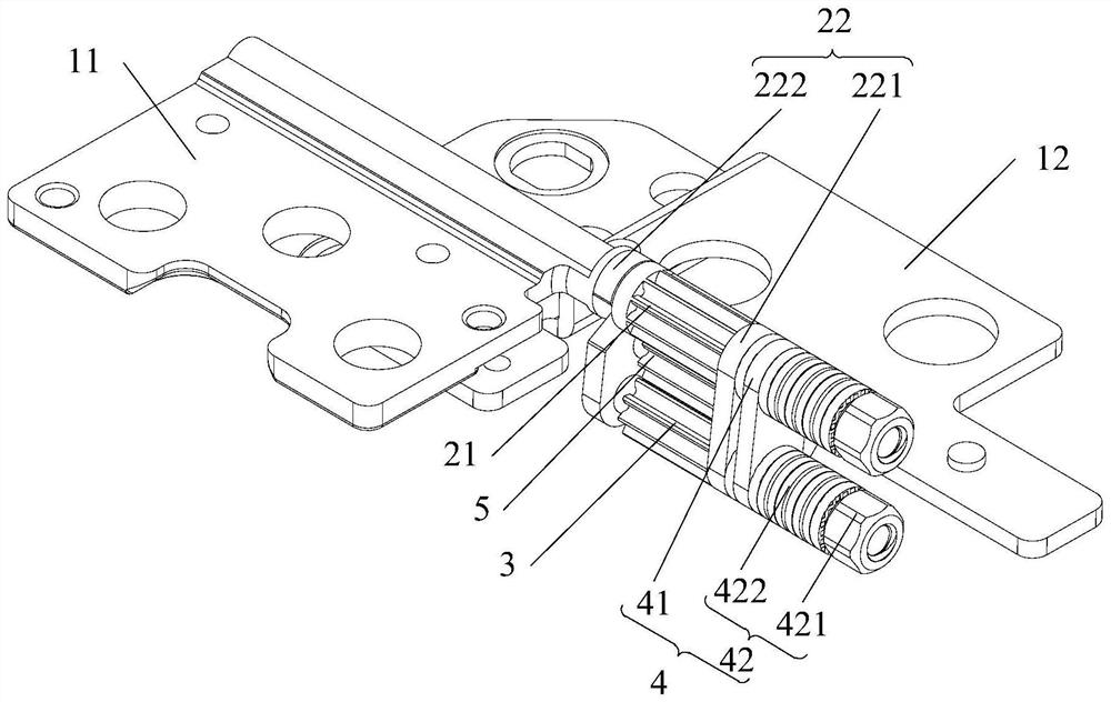
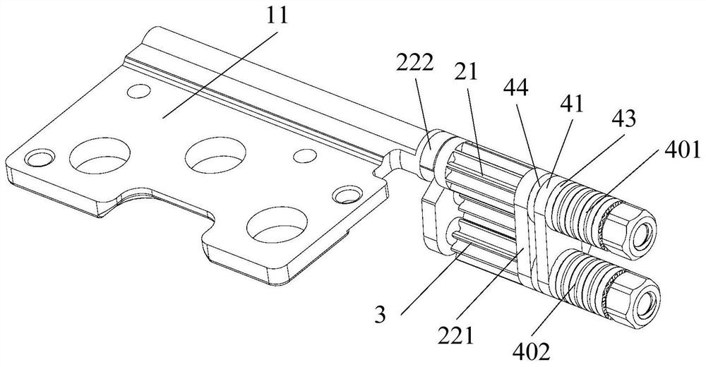
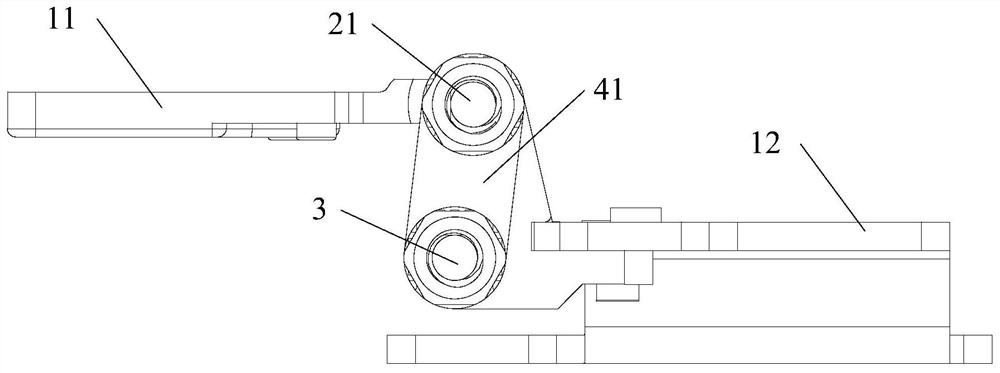
[0045] The first aspect of the present application provides a shaft assembly, such as Figure 1 to Figure 9 As shown, the rotating shaft assembly includes: a first locking part 11 and a second locking part 12...


PUM


Abstract

The invention provides a rotating shaft assembly and electronic equipment, and relates to the technical field of rotating shafts. The rotating shaft assembly comprises a first lock accessory and a second lock accessory; a rotating shaft which comprises a first part and a second part which rotate relatively, wherein the first part is fixedly connected with the first lock accessory, and the second part is fixedly connected with the second lock accessory; a driven part which is connected with the first part or the second part, wherein the rotation of the first part or the second part drives the driven part to rotate; and a torsion mechanism which is at least arranged on the driven part and is used for providing torsion during rotation.

Description

technical field [0001] The present application relates to the technical field of rotating shafts, in particular to a rotating shaft assembly and electronic equipment. Background technique [0002] With the development of technology, the design of notebook computers is becoming thinner and lighter, and the thickness of the display screen is also reduced accordingly. In order to allow the display screen to be connected to the keyboard end in rotation, it is necessary to set a rotating shaft to connect the display screen and the keyboard end. The commonly used design in the prior art is: to set a rotating shaft to connect the keyboard end and the display screen, and at the same time, the rotating shaft can make the display screen fixed at any position . Among them, when the user turns the rotating shaft to any position, the rotating shaft can provide resistance to prevent the rotating shaft from continuing to rotate under the action of inertia or gravity. Since the resistance ...

Claims


Application Information

Patent Timeline
20 Apr 2021
Publication
CN112684853A
IPC
G06F1/16
CPC
G06F1/1681; E05Y2999/00; G06F1/1679; F16C11/10; E05F1/12; E05D3/122
Inventors
谢松佑