Receiver circuit and receiver circuit control method

A receiver and circuit technology, which is applied in the field of receiver circuit and receiver circuit control, can solve problems such as difficult to achieve performance optimization of display driver chips, and achieve the effect of performance optimization

Active Publication Date: 2022-05-31
BEIJING ESWIN COMPUTING TECH CO LTD +1
View PDF0 Cites 0 Cited by
  • Summary
  • Abstract
  • Description
  • Claims
  • Application Information

AI Technical Summary

Problems solved by technology

[0003] The present invention provides a receiver circuit and a receiver circuit control method to solve the problem that it is difficult to optimize the performance of the display driver chip by using the chip pin or the information packet of the timing controller to control the bandwidth of the receiver.

Method used


Image

  • Receiver circuit and receiver circuit control method
  • Receiver circuit and receiver circuit control method
  • Receiver circuit and receiver circuit control method

Examples


Embodiment Construction

[0018] The following will be combined with the accompanying drawings in an embodiment of the present invention, the technical solution in an embodiment of the present invention is clearly and completely described. Obviously, the embodiments described are only a portion of the embodiments of the present invention, and not all embodiments. Based on embodiments in the present invention, all other embodiments obtained by those skilled in the art without making creative labor, are within the scope of protection of the present invention.

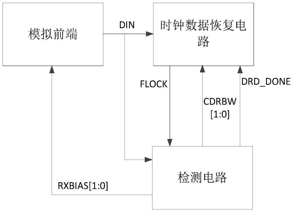
[0019] as Figure 1 As shown, embodiments of the present invention provides a receiver circuit, comprising an analog front end 11, a clock data recovery circuit 12 and a detection circuit 13.

[0020] Analog front end 11 for outputting the first signal.

[0021]Clock data recovery circuit 12 is connected to the analog front end 11. Clock data recovery circuit 12 for locking the frequency of the first signal and output frequency lock signal.

[0022] De...


PUM


Abstract

The invention provides a receiver circuit and a receiver circuit control method. The invention detects the input data through a detection circuit, obtains the data rate detection result, automatically adjusts the bandwidth of the receiver according to the data rate detection result, thereby avoiding the use of chip pins or information packets of the timing controller to control the bandwidth of the receiver, and realizes display The performance of the driver chip is optimized.

Description

Technical field [0001] The present invention relates to the technical field of receiver device, in particular to a receiver circuit and a receiver circuit control method. Background [0002] To support multiple types of application products, more and more display interface protocols cover a wide range of data rates. Receivers that support a wide range of data rates need to support these display interface protocols. In order to consume power efficiency, the receiver needs to set different bandwidths according to the data rate of different input data, where the greater the bandwidth required, the greater the current consumed. In the receiver, the Analog Front-End (AFE) will be confident that the small signal will be amplified into a large signal to clock data recovery circuitry (CDR). In general, there are two common ways to control the bandwidth of a receiver. One is to control it through the chip pin (PIN). The other is controlled by sending a package to the display driver chip v...

Claims


Application Information

Patent Timeline
Patent Type & Authority Patents(China)
IPC IPC(8): H04B1/16H04L41/0896
CPCH04B1/16H04B1/18H04L41/0896
Inventor 花正贝李东明南帐镇白东勋范昊
Owner BEIJING ESWIN COMPUTING TECH CO LTD
Why Eureka
Try Eureka