
Integrated optimization structure of separation assembly

A technology for optimizing structures and components, applied to furniture parts, household appliances, drawers, etc., can solve the problems of complex structure of partition components, poor assembly stability, inconvenient disassembly and assembly by users, etc.

Pending Publication Date: 2021-04-23
GUANGDONG DTC HARDWARE PRECISION MFG CO LTD
View PDF1 Cites 3 Cited by
  • Summary
  • Abstract
  • Description
  • Claims
  • Application Information

AI Technical Summary

Problems solved by technology

[0003] The purpose of the present invention is to provide an integrated and optimized structure of the partition assembly to overcome the disadvantages of the prior art that the partition assembly is complex in structure, inconvenient for users to disassemble and assemble, and poor assembly stability

Method used


Image

  • Integrated optimization structure of separation assembly
  • Integrated optimization structure of separation assembly
  • Integrated optimization structure of separation assembly

Examples


no. 1 example

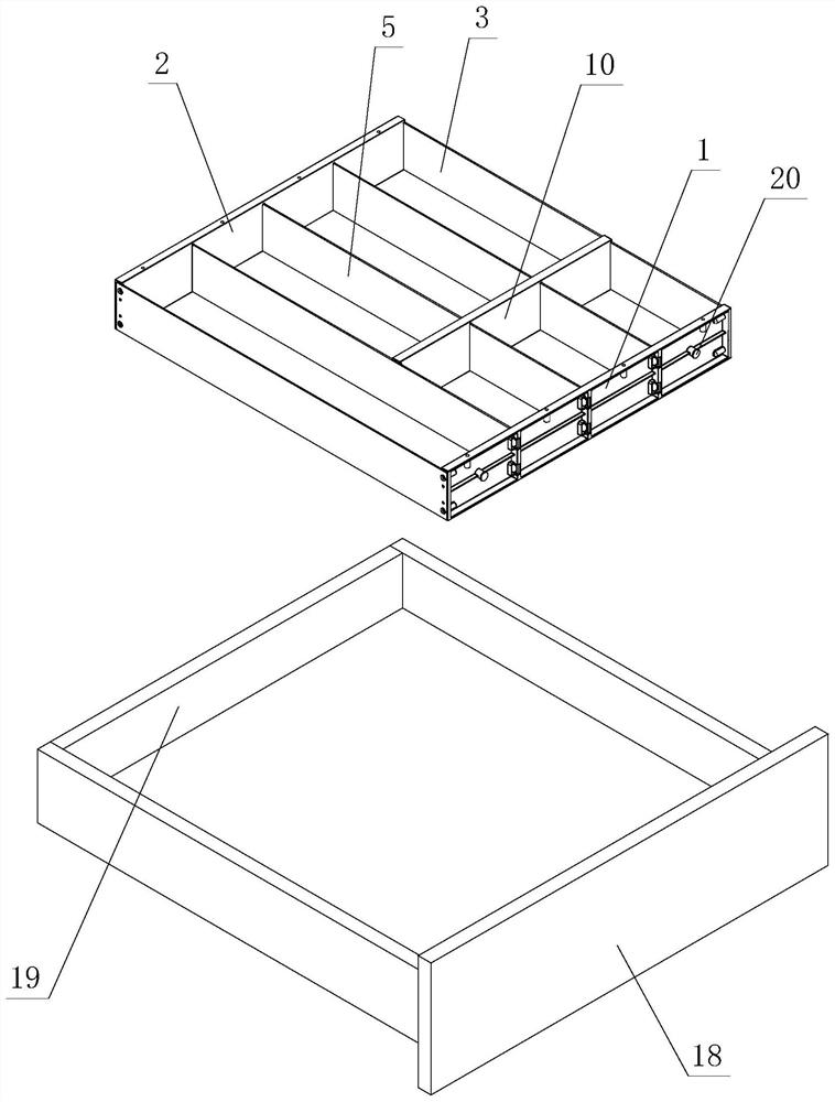
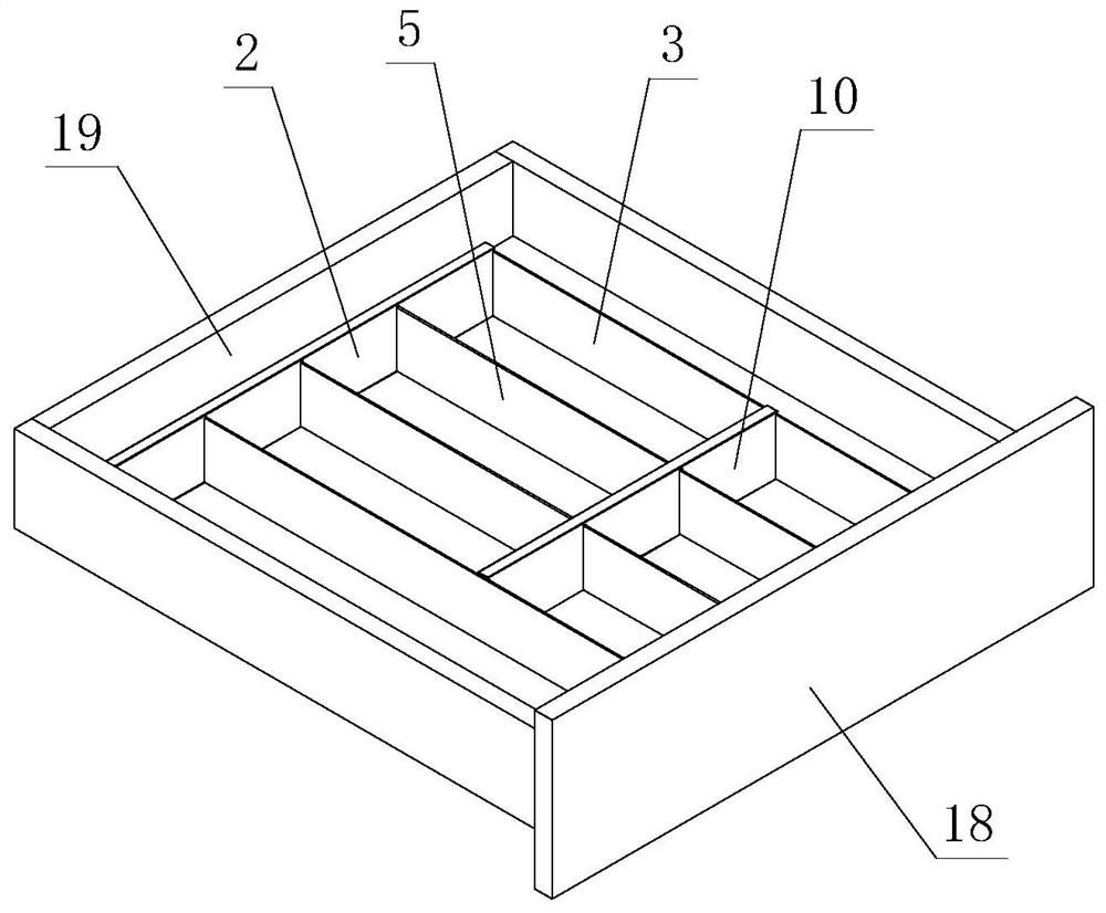
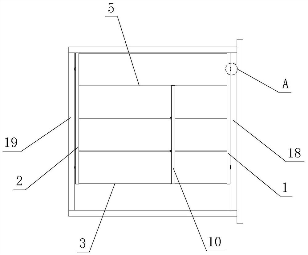
[0043] see Figure 1-Figure 15, the integrated optimization structure of the partition assembly, the partition assembly includes a front panel 1, a rear panel 2 and a left and right side panel 3, and the left and right side panels 3 are respectively detachably and fixedly connected to the left and right sides of the front panel 1 and the rear panel 2, and After being fixed, storage cavities are formed between each other, the front plate 1 and the rear plate 2 are respectively provided with limiting assembly grooves 4, and at least one partition plate 5 that separates the storage cavity is detachable through the limiting assembly grooves 4; The partition plate 5 is detachably arranged on the limit assembly groove 4 from the side, and is basically parallel to the left and right side plates 3 when assembled.

[0044] Specifically, the limit assembly groove 4 is oppositely arranged on the front plate 1 and the rear plate 2, wherein the inside of the limit assembly groove 4 is basi...

no. 2 example

[0062] see Figure 16 , Figure 17 , the integrated optimization structure of this partition assembly is different from the first embodiment in that: the middle plate 10 is provided with a sliding anchoring part 14, and the sliding anchoring part 14 is infinitely adjustable and detachably arranged on the adjacent partition. between the plates 5, and / or between the partition plate 5 and the left and right side plates 3.

[0063] Other unmentioned parts are the same as the first embodiment.

no. 3 example

[0065] see Figure 18 , Figure 19 , the integrated optimization structure of the partition assembly, it is different from the first embodiment in that: between the adjacent partition boards 5, and / or between the partition board 5 and the left and right side boards 3 are provided with several clip joints part 15, the middle plate 10 is provided with a snap-fit ​​part 16, and is detachably arranged on several snap-fit ​​parts 15 through the step-by-step adjustment of the snap-fit ​​part 16 .

[0066] Other unmentioned parts are the same as the first embodiment.


PUM


Abstract

An integrated optimization structure of a partition assembly comprises a front plate, a rear plate, a left side plate and a right side plate; the left side plate and the right side plate are detachably and fixedly connected with the left side and the right side of the front plate and the rear plate respectively, and a containing cavity is formed between the left side plate and the right side plate after fixing. limiting assembly grooves are formed in the front plate and the rear plate correspondingly, and at least one partition plate for partitioning the containing cavity is detachably arranged through the limiting assembly grooves; the partition plate is detachably arranged on the limiting assembling groove from the side portion and is basically parallel to the left side plate and the right side plate in the assembling process. Through the improvement of the structure, the assembly firmness of the separation assembly can be improved; meanwhile, the space of the storage cavity can be separated, a user can freely splice and assemble multiple separation areas of different sizes according to actual use requirements, and the areas of the separation areas can be adjusted at will; therefore, the space utilization rate of the storage cavity is effectively improved, the requirements for classified storage of different tableware, dressing cases and articles of various sizes are met, and flexibility and variability are achieved.

Description

technical field [0001] The invention relates to an integrated optimization structure of a partition assembly. Background technique [0002] The Chinese patent document number is CN209712159U, which discloses a partition assembly on December 3, 2019, which includes a first connector, a second connector and a partition plate, and each partition plate is provided with a first connection groove, separating Both ends of the board are respectively provided with first connecting holes, the first connecting piece is arranged in the first connecting hole of the first partition plate, the second connecting piece is connected with the first connecting piece, and the second connecting piece is arranged on the second connecting piece. In the first connecting groove of the partition plate. It is said that the second connecting piece of the above structure can move along the first connecting groove to drive the first partition plate to move to realize the adjustment of the area of ​​the p...

Claims


Application Information

Patent Timeline
Patent Type & Authority Applications(China)
IPC IPC(8): A47B88/969
CPCA47B88/969
Inventor 伍志勇
Owner GUANGDONG DTC HARDWARE PRECISION MFG CO LTD
Learn More