Slipway and ship transfer method

A technology for berths and ships, which is applied in the direction of berths, ships, transportation and packaging, etc., and can solve problems such as high cost and ecological damage

Pending Publication Date: 2021-04-27
浙江华航实业有限公司
View PDF0 Cites 1 Cited by
  • Summary
  • Abstract
  • Description
  • Claims
  • Application Information

AI Technical Summary

Problems solved by technology

[0005] Aiming at the deficiencies of the prior art, the present invention provides a slipway and a ship transfer method, through which the ship can be transferred from the water stably and without deformation to the land for maintenance, which solves the cost of using docks for maintenance in the prior art High, ecologically destructive issues

Method used


Image

  • Slipway and ship transfer method
  • Slipway and ship transfer method
  • Slipway and ship transfer method

Examples


Embodiment 1

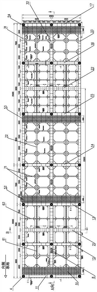
[0061] Embodiment 1 This embodiment provides a slipway, including a frame body, a connecting structure and a lifting mechanism arranged at the bottom of the frame body. Such as figure 1 As shown, the frame body is a rectangular single-layer truss structure, with the length direction of the frame body as the longitudinal direction. At least one longitudinal middle rod and horizontal middle rod are respectively distributed between the beams, and the longitudinal beams, cross beams, longitudinal middle rods, and horizontal middle rods are made of steel materials. In order to ensure the structural strength of the frame, the length of the frame can be adjusted according to the hull length of the corresponding ship. For example, when it is applied to a ship with a hull length of less than 25m, the frame can be composed of at least 3 longitudinal beams and at least 5 beams; When applied to ships with a hull length of 50~65m, such as figure 1 As shown, it is equipped with 3 longitud...

Embodiment 2

[0074] Embodiment 2 The difference between this embodiment and Embodiment 1 is that the combination figure 1 right side and Figure 9 , Figure 10 As shown, in this embodiment, the frame body corresponds to the front end of the ship and has at least one side support mechanism on both lateral sides (see Figure 11 shown): as Figure 10 As shown, part of the upper surface of the sub-beam six between the first and second longitudinal beams, and between the second and third longitudinal beams is provided with an upper slot structure—that is, an open design, in which the second hydraulic rod is installed 1. Support rod, one end of the support rod is hinged to the side of the auxiliary beam six close to the second longitudinal beam, and the other end of the support rod is close to a certain point in the middle ( figure 1 The example in the example is 400mm away from the other end) and the movable end of the hydraulic rod is hinged, and the other end of the hydraulic rod is hinged...

Embodiment 3

[0075] Embodiment 3 The difference between this embodiment and Embodiment 1 is that a support adjustment mechanism is provided (see Figure 17 shown): Combined figure 1 left and Figure 4 As shown, the upper part of the sub-beam is also provided with an upward slot—that is, an open design, which allows the sub-beam to be connected to the outside world and can be installed inside it. Raised third hydraulic lever. The third hydraulic rod can extend upwards and touch the bottom of the rear side of the ship to assist in fixing the ship.

[0076] In this embodiment, a two-way universal joint vertical output structure is used in combination with a translation screw and a translation handwheel, such as Figure 17 The translation structure shown in , enables the third hydraulic rod to move appropriately in the slot in the length direction of the auxiliary beam.


PUM


Abstract

The invention provides a slipway and a ship transfer method, and belongs to the technical field of ships, the slipway comprises a frame body with an upper surface for berthing of a ship, a connecting structure matched with a carrying device and detachably or movably connected, and a lifting mechanism for lifting the frame body and the ship on the frame body together. By applying the slipway, the ship can be stably transferred to the shore without deformation, the operation cost can be greatly reduced, damage to natural ecology due to construction of a dry dock and use of a floating dock is avoided, and the slipway is economical, environmentally friendly, low in energy consumption and practical.

Description

technical field [0001] The invention relates to the technical field of ship maintenance, in particular to a transfer berth and a ship transfer method. Background technique [0002] At present, dry docks or floating docks are required for maintenance of deep-draft ships such as large fishing boats and scientific research ships. On the one hand, due to the high cost and excessive cost of dry docks and floating docks, on the other hand, both dry docks and floating docks will cause damage to the environment and ecology and have a limited service life. Therefore, current national policies and environmental protection associations do not encourage Shipyards or qualified maintenance companies build dry docks or floating docks for maintenance. Therefore, where to repair ships in the future becomes a difficult point. [0003] A feasible method is to tow the ship to the shore for maintenance. For small ships (usually within 25m), the hull is small and easy to tow, but for medium-siz...

Claims


Application Information

Patent Timeline
Patent Type & Authority Applications(China)
IPC IPC(8): B63C3/00B63C3/12B63B81/00
CPCB63C3/00B63C3/12B63B81/00
Inventor 周多数周凯扬
Owner 浙江华航实业有限公司
Why Eureka
Try Eureka