
Turnover tool for transferring of spring operating mechanism

A technology of operating mechanism and flipping tooling, which is applied in hoisting devices, lifting devices, etc., and can solve problems such as poor safety

Active Publication Date: 2021-04-27
HENAN PINGGAO ELECTRIC +2
View PDF13 Cites 0 Cited by
  • Summary
  • Abstract
  • Description
  • Claims
  • Application Information

AI Technical Summary

Problems solved by technology

[0004] The purpose of the present invention is to provide a turning tool for spring operating mechanism transfer, so as to solve the technical problem of poor safety when manually pulling the turning spring operating mechanism in the prior art

Method used


Image

  • Turnover tool for transferring of spring operating mechanism
  • Turnover tool for transferring of spring operating mechanism
  • Turnover tool for transferring of spring operating mechanism

Examples


specific Embodiment 1

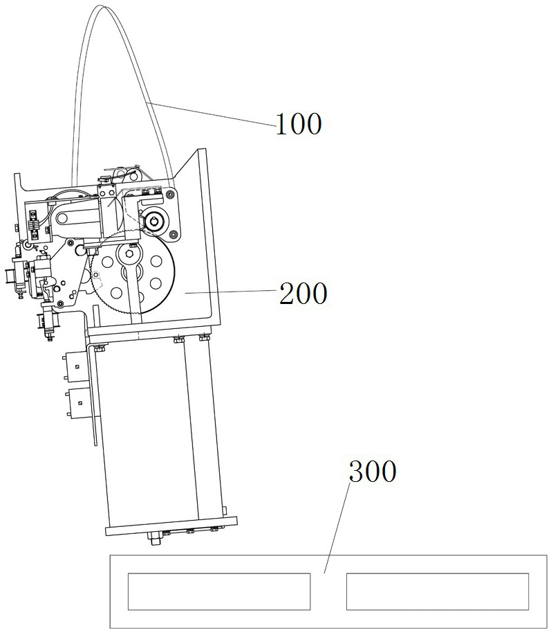
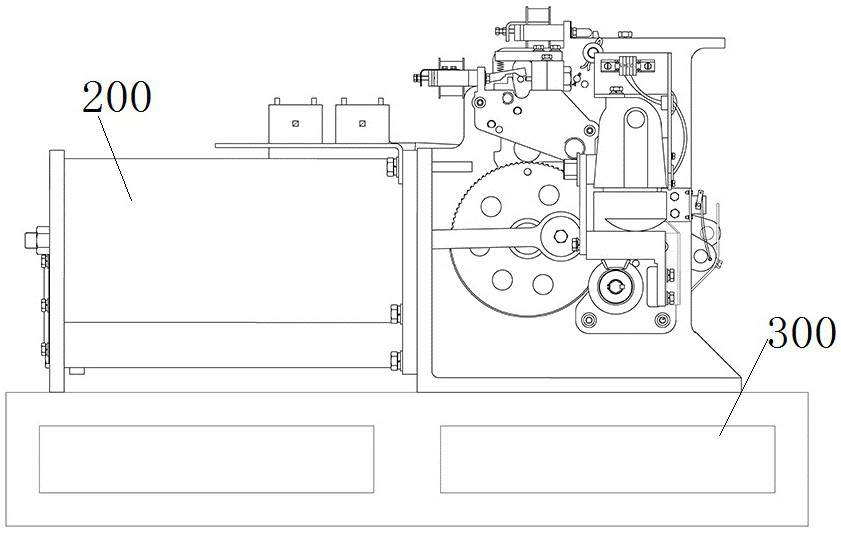
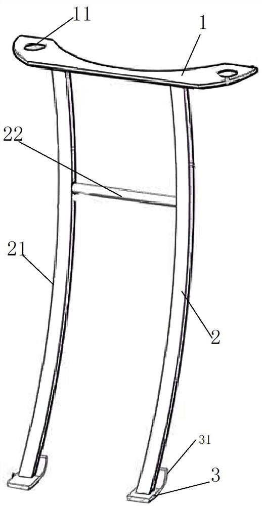
[0042] In the spring operating mechanism transfer tooling, the middle leg 2 extends obliquely in the up and down direction in the form of an arc curve, so that the upper connecting part and the lower supporting leg are arranged in a horizontal dislocation, and the upper connecting part is fixedly assembled with the spring operating mechanism 200 and When the spring operating mechanism 200 is lifted vertically, the center of gravity of the spring operating mechanism 200 is located on the side of the lower supporting foot, and when the spring operating mechanism 200 is lowered, the spring operating mechanism 200 can be turned around the turning fulcrum under the action of gravity , to complete the overturning of the spring operating mechanism 200 and place it horizontally on the transfer tray 300 .

[0043] The structure of the flipping tooling for the transfer of the spring operating mechanism is as follows: Figure 3 to Figure 5As shown, it includes a middle leg 2, the top of ...

specific Embodiment 2

[0052] It differs from Embodiment 1 mainly in that: in Embodiment 1, the middle leg extends along the up and down direction in the form of a circular arc curve. In this embodiment, the middle leg extends in a straight line along the up-and-down direction, and it is only necessary to ensure that the upper connecting portion and the lower supporting leg are misaligned in the horizontal direction.

specific Embodiment 3

[0054] It differs from Embodiment 1 mainly in that: in Embodiment 1, the middle leg extends along the up and down direction in the form of a circular arc curve. In this embodiment, it is also possible to set the folding line bending part on the middle leg, for example, design it as a zigzag structure, so as to ensure that the upper connecting part and the lower supporting leg are misaligned in the horizontal direction.


PUM


Abstract

The invention relates to a turnover tool for transferring of a spring operating mechanism. The turnover tool comprises an upper connecting part which is detachably and fixedly assembled with the bottom of the spring operating mechanism; lower supporting legs used for downwards abutting against the corresponding foundations to form a turnover supporting point; and a middle supporting leg which obliquely extends in a transition mode in the vertical direction or is provided with a broken line bending part; and the upper connecting part and the lower supporting legs are distributed in a staggered mode in the horizontal direction, when the upper connecting part and the spring operating mechanism are fixedly assembled and the spring operating mechanism is vertically hoisted, the gravity center of the spring operating mechanism is located on one sides of the lower supporting legs, when the spring operating mechanism is lowered, the spring operating mechanism can turn around the turnover supporting point under the action of gravity. Due to the fact that the middle supporting leg obliquely extends in a transition mode in the vertical direction or is provided with the broken line bending part, the upper connecting part and the lower supporting legs are distributed in a staggered mode in the horizontal direction, the gravity center of the spring operating mechanism is conveniently guided to force the spring operating mechanism to automatically turn over with the turning supporting point as the basis, manual pulling is not needed, and safety and reliability are achieved.

Description

technical field [0001] The invention relates to a turning tool for transferring a spring operating mechanism. Background technique [0002] For the spring operating mechanism, it needs to be hoisted to the test bench for testing before leaving the factory. During the test, the spring operating mechanism is in a vertical state. After the test is completed, it is hoisted to the transfer pallet of the transfer vehicle. Generally speaking, as figure 2 As shown, the spring operating mechanism is fixed on the transfer pallet in a horizontal posture, therefore, it is necessary to turn the spring operating mechanism in a vertical posture to a horizontal posture during hoisting and transportation. [0003] At present, the following two ways are often used to overturn the spring operating mechanism: the one is manual overturning. Such as figure 1 As shown, the spring operating mechanism is lifted away from the test bench by the crane using the sling, and after the lower part of th...

Claims


Application Information

Patent Timeline
IPC IPC(8): B66F19/00
CPCB66F19/00
Inventor 范曙光郑晓春王东亮李铁付亚旭王志峰郭锴汪盛朱清杰晋志英吕晓峰许莹王慧慧李淑华
Owner HENAN PINGGAO ELECTRIC
Learn More