Textile cloth cleaning device

A cleaning device and textile cloth technology, which is applied in textiles and papermaking, textile material treatment, spray/jet textile material treatment, etc., can solve the problem that the dirt on the surface of textile cloth cannot be effectively removed

Active Publication Date: 2021-04-27
SHAOXING UNIV YUANPEI COLLEGE
View PDF4 Cites 5 Cited by
  • Summary
  • Abstract
  • Description
  • Claims
  • Application Information

AI Technical Summary

Problems solved by technology

[0005] In order to overcome the technical problem in the prior art that the cleaning device with a fixed nozzle outlet angle cannot effectively remove the dirt on the surface of the textile cloth, the present invention provides a textile cloth cleaning device. The surface dirt is easier to be removed. In addition, this application can use a single nozzle to realize repeated sweeping and cleaning of the cloth in the same water outlet cycle, compared with the single nozzle in the prior art in the same water outlet cycle. Cleaning, the cleaning efficiency of textile cloth is greatly improved

Method used


Image

  • Textile cloth cleaning device
  • Textile cloth cleaning device
  • Textile cloth cleaning device

Examples


Embodiment 1

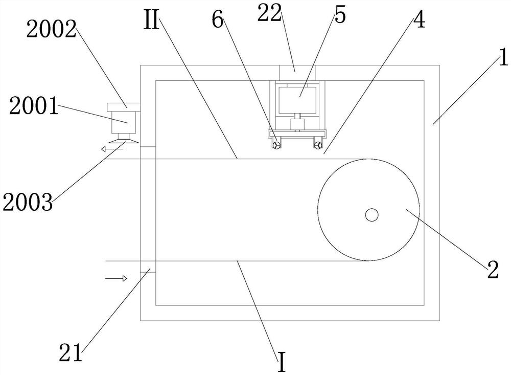
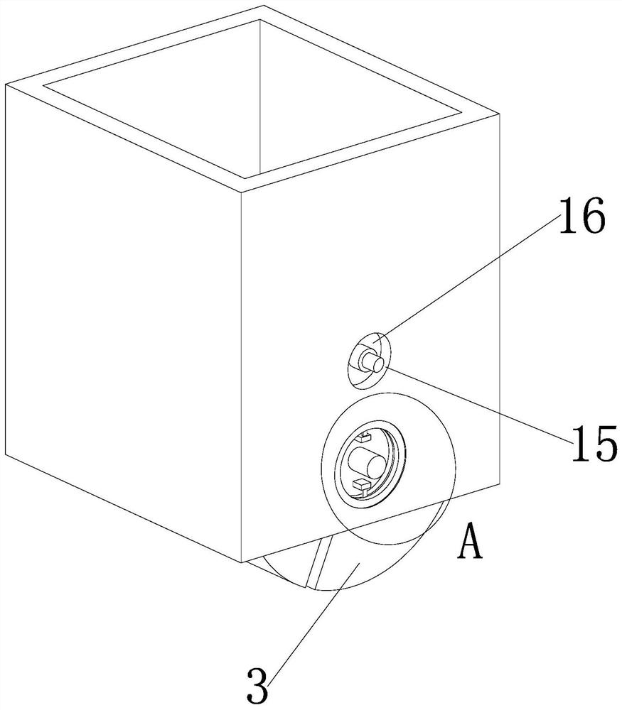
[0032] Such as Figure 1 to Figure 7As shown, a textile cleaning device includes a housing 1, a tensioning cylinder 2 and a flushing mechanism 3 are arranged in the casing, a spray gap 4 exists between the flushing mechanism and the textile cloth, and the flushing mechanism includes a water supply assembly 5 and a water spray Assembly 6, the water supply assembly includes a water tank 601 and a water pump 602, the water spray assembly includes a nozzle pipe 7 and a nozzle 8, the nozzle includes a body 801 and a water spray channel 802, and the water spray channel includes an inlet water channel 8021 and an outlet water channel 8022. One end of the water channel communicates with the nozzle pipe, the other end of the water inlet channel communicates with one end of the water outlet channel, and the other end of the water outlet channel faces the textile fabric. The water pump delivers the cleaning liquid in the water tank to the nozzle pipe. The cleaning liquid only flows outwa...

Embodiment 2

[0036] Such as Figure 7 As shown, the inner wall of the feeding port is fixedly connected with a mounting bracket, and the right side of the mounting bracket is provided with two vertical plates, and the two vertical plates are fixedly connected through a water tank. The top of the water tank is connected with a flushing shell through a water pump, and the flushing shell The water spray assembly is installed on the top of the water spray assembly, and the detailed structure diagram of the water spray assembly can be viewed Figure 6 , it can be clearly seen from the accompanying drawings in the specification that there are two flushing shells inside the entire shell and a water spray assembly arranged on the flushing shells, so that the two sides of the textile fabric can be directly cleaned synchronously. That is, there are two working mechanisms installed inside the housing. The working mechanisms specifically include: water tank, riser, flushing shell, water pump and water...

Embodiment 1

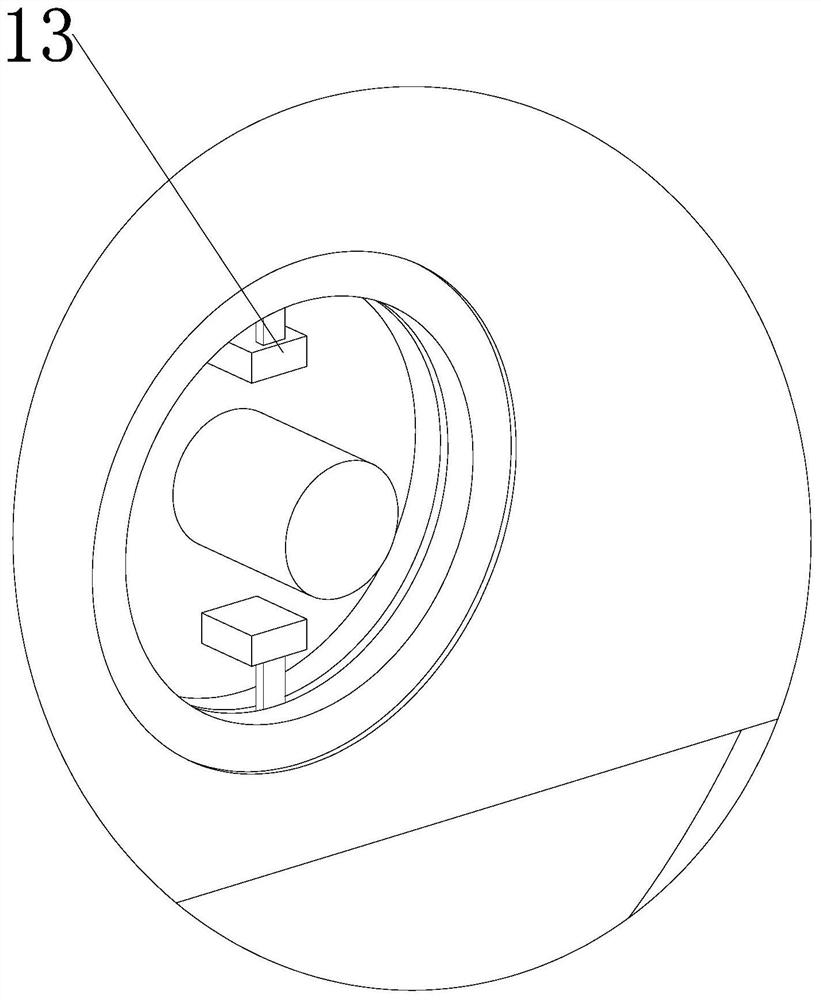
[0037] Embodiment 1 When in use, the water pump absorbs the water inside the water tank through the water suction pipe and injects the water into the inside of the flushing shell through the water outlet pipe, and then the water flow enters the inside of the water spray assembly, and the motor drives the drive gear to rotate through the drive shaft, and the drive gear passes through the chain It drives the driven gear to rotate, and the driven gear drives the sealing plate to rotate through the central shaft. The rotation of the sealing plate will cause the two stable plates to move. The sealing plate drives the sealing block to move through the fixed rod, and the three sealing blocks move. From the figure, the water flow It will flow in from the upper left "channel" and flow out from the lower left "channel". Then the three sealing blocks are moving. From the picture, the three sealing blocks cooperate to form a mechanism similar to a cylinder. , the cylinder mechanism rotates...


PUM


Abstract

In order to solve the technical problem that in the prior art, a cleaning device with the fixed water outlet angle of a spray head cannot effectively remove dirt on the surface of textile cloth, a textile cloth cleaning device is provided. The textile cloth cleaning device comprises a shell; a tightening cylinder and a flushing mechanism are arranged in the shell; a spraying gap exists between the flushing mechanism and the textile cloth; the flushing mechanism comprises a water supply assembly and a water spraying assembly; the water supply assembly comprises a water tank and a water pump; the water spraying assembly comprises a spraying head pipe and a spraying head; the spraying head comprises a body and a water spraying flow channel; the water spraying flow channel comprises a water inlet flow channel and a water outlet flow channel; one end of the water inlet flow channel communicates with the spray head pipe, and the other end of the water inlet flow channel communicates with one end of the water outlet flow channel; the other end of the water outlet flow channel faces the textile fabric; the water pump conveys cleaning liquid in the water tank into the spray head pipe, and the cleaning liquid in the spray head pipe only flows outwards along the water spraying flow channel; and a driving assembly for driving the spray head to rotate is arranged on the spray head pipe. Multiple times of repeated sweeping and cleaning of the cloth in the same water outlet period can be achieved through the single spray head.

Description

technical field [0001] The invention relates to the technical field of textile cleaning, in particular to a textile cleaning device. Background technique [0002] Knitted fabrics are divided into two types according to the weaving method: weft-knitted fabrics and warp-knitted fabrics. Weft-knitted fabrics are often made of low-elastic polyester yarn or special-shaped polyester yarn, nylon yarn, cotton yarn, wool yarn, etc. Loop weaves, etc. are woven on various weft knitting machines. In the process of cleaning textile cloth, the cleaning effect of existing cloth cleaning devices is not good. [0003] The announcement number is CN207047516U, and the patent announcement date is 2018.02.27 discloses a textile cloth cleaning device for textile cloth production, including a base, and the top of the base is sequentially installed with a hydraulic lifting device, a water tank and a cleaning tank from left to right. A tension adjustment roller is installed on the top of the hydra...

Claims


Application Information

Patent Timeline
Patent Type & Authority Applications(China)
IPC IPC(8): D06B1/02D06B1/12D06B15/09
CPCD06B1/02D06B1/12D06B15/09
Inventor 潘慧
Owner SHAOXING UNIV YUANPEI COLLEGE
Why Eureka
Try Eureka