A textile cleaning device
A cleaning device and textile cloth technology, which is applied in textiles and papermaking, textile material treatment, spray/jet textile material treatment, etc., can solve the problem that the surface dirt of textile cloth cannot be effectively removed, so as to improve the cleanliness and ensure reliability sexual effect
- Summary
- Abstract
- Description
- Claims
- Application Information
AI Technical Summary
Problems solved by technology
Method used
Image

Examples
Embodiment 1
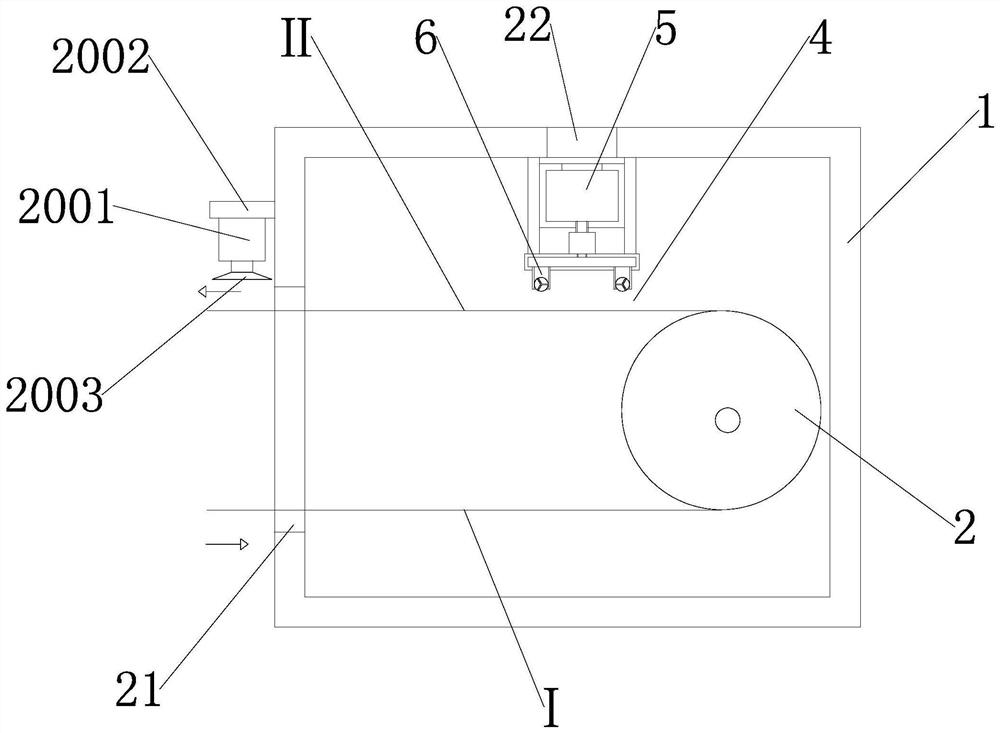
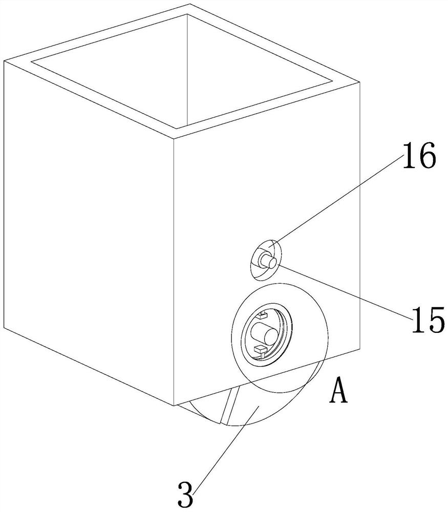
[0032] like Figure 1 to Figure 7As shown, a textile cloth cleaning device includes a casing 1, a tensioning cylinder 2 and a flushing mechanism 3 are arranged in the casing, a spray gap 4 exists between the flushing mechanism and the textile cloth, and the flushing mechanism includes a water supply assembly 5 and a water spray Assembly 6, the water supply assembly includes a water tank 601 and a water pump 602, the water spray assembly includes a spray head pipe 7 and a spray head 8, the spray head includes a body 801 and a water spray channel 802, and the water spray channel includes a water inlet channel 8021 and a water outlet channel 8022. One end of the water flow channel is connected with the nozzle pipe, the other end of the water inlet channel is connected with one end of the water outlet channel, and the other end of the water outlet channel is facing the textile cloth. The cleaning liquid only flows outward along the water spray channel, and the nozzle pipe is provi...
Embodiment 2
[0036] like Figure 7 As shown in the figure, a mounting bracket is fixedly connected to the inner wall of the feeding port, and two vertical plates are arranged on the right side of the mounting bracket. The two vertical plates are fixedly connected by a water tank. The top of the water tank is connected with a flushing shell through a water pump. There is a water spray assembly installed on the top of the Image 6 , it can be clearly seen from the accompanying drawings in the description that two flushing shells and a water spray component arranged on the flushing shell are arranged inside the entire shell, so that synchronous cleaning can be performed directly on both sides of the textile cloth. There are two working mechanisms installed inside the shell. The working mechanisms include: water tank, vertical plate, flushing shell, water pump and water spray assembly. It should be noted here that the water tank filling port on the right side of the mounting bracket is opened ...
Embodiment 1
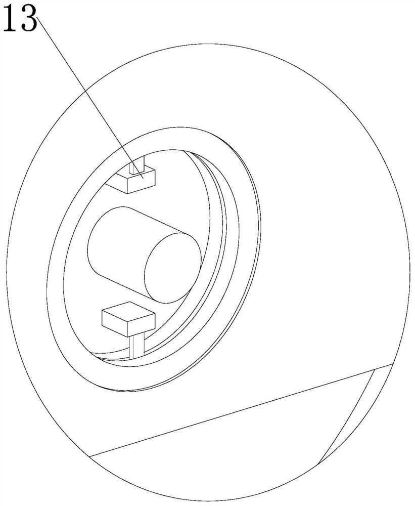
[0037] Example 1 When in use, the water pump absorbs the water inside the water tank through the water suction pipe and injects the water into the inside of the flushing shell through the water outlet pipe, after which the water flow will enter the inside of the water spray assembly, the motor drives the driving gear to rotate through the driving shaft, and the driving gear passes through the chain. Drive the driven gear to rotate, the driven gear drives the sealing plate to rotate through the central shaft, the rotation of the sealing plate will cause the movement of two stable plates, the sealing plate drives the movement of the sealing block through the fixed rod, and the three sealing blocks move. From the picture, the water flow It will flow in from the water flow "channel" at the upper left and flow out from the water flow "channel" at the lower left, then the three sealing blocks are moving. From the picture, the three sealing blocks cooperate to form a cylinder-like mech...
PUM
 Abstract
Description
Claims
Application Information
 - R&D
- Intellectual Property
- Life Sciences
- Materials
- Tech Scout
- Unparalleled Data Quality
- Higher Quality Content
- 60% Fewer Hallucinations
Browse by: Latest US Patents, China's latest patents, Technical Efficacy Thesaurus, Application Domain, Technology Topic, Popular Technical Reports.
© 2025 PatSnap. All rights reserved.Legal|Privacy policy|Modern Slavery Act Transparency Statement|Sitemap|About US| Contact US: help@patsnap.com