
Power distribution cabinet with dust removal and heat dissipation structure

A technology of heat dissipation structure and power distribution cabinet, applied in substation/distribution device casing, electrical components, substation/switch layout details, etc. Efficient cooling effect

Active Publication Date: 2021-04-27
SHANDONG OUMA JIABAO ELECTRIC TECH CO LTD
View PDF4 Cites 6 Cited by
  • Summary
  • Abstract
  • Description
  • Claims
  • Application Information

AI Technical Summary

Problems solved by technology

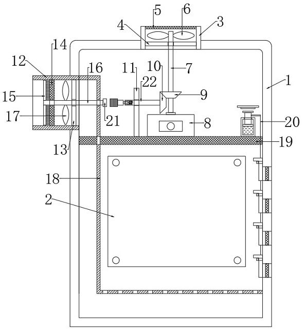
[0003] Most of the existing heat dissipation methods for power distribution cabinets are provided by setting heat dissipation holes on the power distribution cabinet, and installing dust-proof nets in the heat dissipation holes to reduce dust entering the power distribution cabinet. In the prior art, there are also power distribution cabinets that use fans to dissipate heat. The heat dissipation efficiency has been improved, but the heat dissipation effect is still not good, and the dust-proof net needs to be cleaned regularly by the management personnel to ensure the normal heat dissipation of the power distribution cabinet, which increases the workload of the management personnel, so we designed a A power distribution cabinet with dust removal and heat dissipation structure to solve the above problems

Method used


Image

  • Power distribution cabinet with dust removal and heat dissipation structure
  • Power distribution cabinet with dust removal and heat dissipation structure
  • Power distribution cabinet with dust removal and heat dissipation structure

Examples


Embodiment Construction

[0024] The following will clearly and completely describe the technical solutions in the embodiments of the present invention with reference to the accompanying drawings in the embodiments of the present invention. Obviously, the described embodiments are only some, not all, embodiments of the present invention.

[0025] In describing the present invention, it should be understood that the terms "upper", "lower", "front", "rear", "left", "right", "top", "bottom", "inner", " The orientation or positional relationship indicated by "outside", "front end", "rear end", "both ends", "one end" and "the other end" are based on the orientation or positional relationship shown in the drawings, and are only for the convenience of describing this The invention and the simplified description do not indicate or imply that the device or element referred to must have a specific orientation, be constructed and operate in a specific orientation, and thus should not be construed as limiting the p...


PUM


Abstract

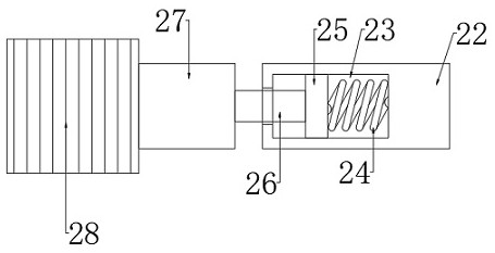
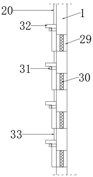
The invention discloses a power distribution cabinet with a dust removal and heat dissipation structure. The power distribution cabinet comprises a power distribution cabinet body, wherein electrical equipment and a screen plate are installed in the power distribution cabinet body, the screen plate is located above the electrical equipment, a first installation frame is arranged at the upper end of the power distribution cabinet body in a penetrating mode, and a cross rod and a first dustproof net are installed in the first installation frame; the first dustproof net is located above the transverse rod, a driving motor is installed on the net plate, the output end of the driving motor is fixedly connected with a rotating rod, the rotating rod penetrates through the transverse rod and is fixedly connected with the transverse rod, a plurality of first fan blades are fixedly connected to the rotating rod, and a second installation frame is installed on one side of the power distribution cabinet in a penetrating mode; and a second dustproof net and a vertical rod are mounted in the second mounting frame. The dustproof device is reasonable in structure, the second dustproof net can be automatically cleaned according to actual conditions, the labor amount of managers is greatly reduced, meanwhile, the heat dissipation effect on electrical equipment is better, and stable work of the electrical equipment is guaranteed.

Description

technical field [0001] The invention relates to the technical field of power distribution cabinets, in particular to a power distribution cabinet with dust removal and heat dissipation structures. Background technique [0002] Power distribution cabinets are divided into power distribution cabinets, lighting distribution cabinets, and metering cabinets. They are the final equipment of the power distribution system. Power distribution cabinets are collectively referred to as motor control centers. ; The motor control center is used in the occasions where the load is concentrated and there are many circuits. They distribute the electric energy of a certain circuit of the upper-level power distribution equipment to the nearby load. This level of equipment should provide protection, monitoring and control for the load. All electrical components and lines should be in good contact and connected reliably; there should be no serious heating or burning, and the door of the switchboa...

Claims


Application Information

Patent Timeline
Patent Type & Authority Applications(China)
IPC IPC(8): H02B1/30H02B1/56H02B1/28
CPCH02B1/30H02B1/565H02B1/28
Inventor 王先平
Owner SHANDONG OUMA JIABAO ELECTRIC TECH CO LTD
Learn More