Stator assembly and motor
A stator and component technology, applied in the direction of electric components, electrical components, electromechanical devices, etc., can solve the problems of affecting the performance of the motor and the lack of coaxiality of the central cavity, so as to ensure the uniformity of the air gap, improve the coaxial accuracy, and ensure the same The effect of axis accuracy
- Summary
- Abstract
- Description
- Claims
- Application Information
AI Technical Summary
Problems solved by technology
Method used
Image
Examples
Embodiment 1
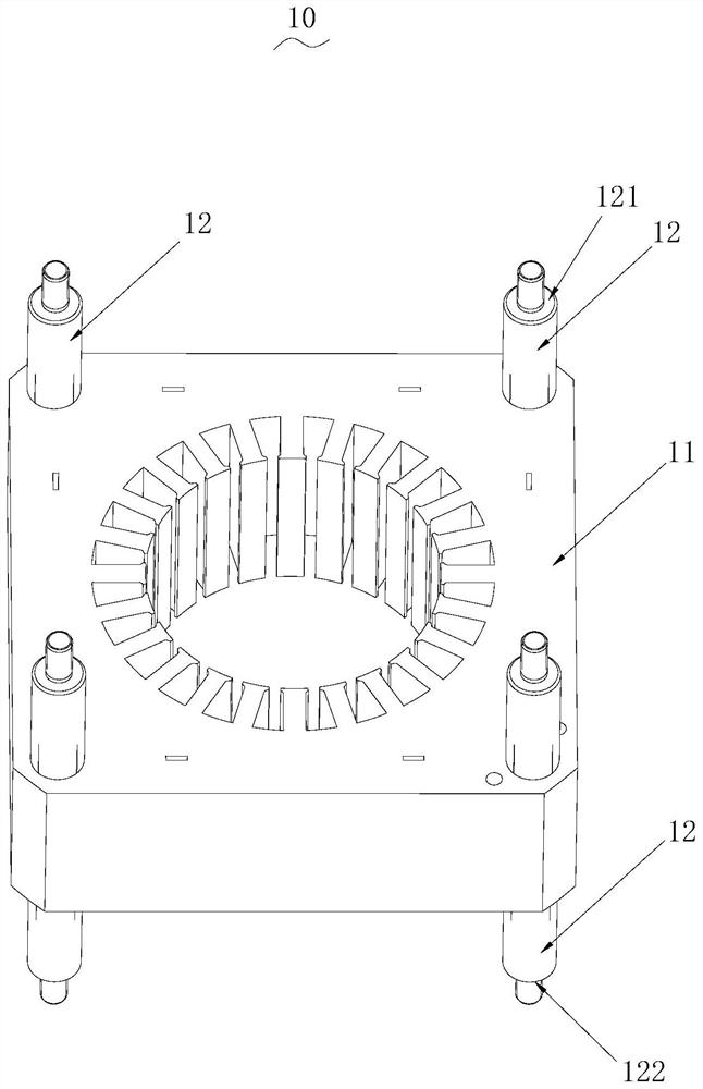
[0049] see figure 1 , the stator assembly 10 provided by the present application will now be described. The stator assembly 10 is applied in a motor.
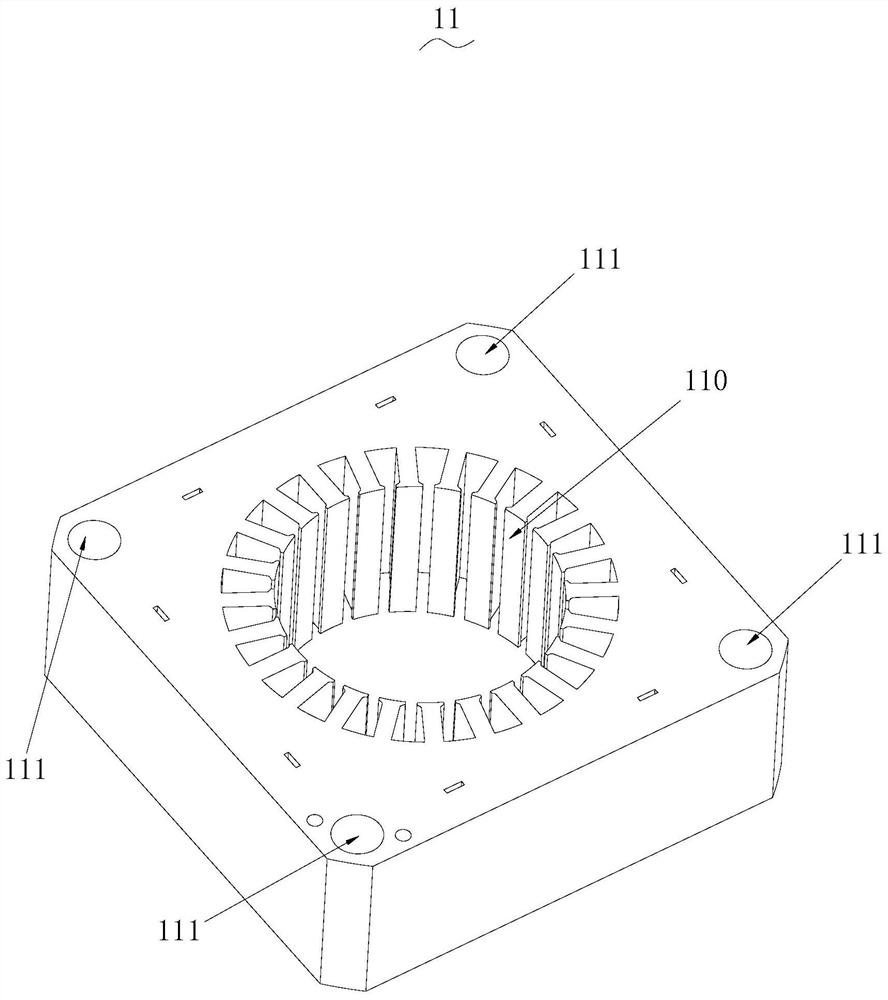
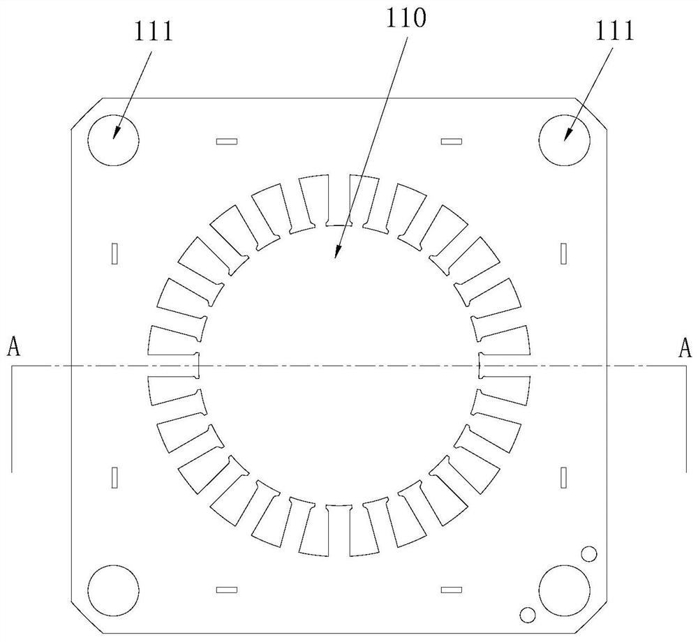
[0050] The stator assembly 10 includes a stator core 11 and a plurality of supporting structures 12 . see figure 2 and image 3 , the stator core 11 has a central cavity 110 and a plurality of mounting grooves 111, the central cavity 110 and a plurality of mounting grooves 111 extend axially, each mounting groove 111 is arranged around the central cavity 110, and each mounting groove 111 is axially connected to the central cavity 110 parallel to each other. Each support structure 12 is fixedly installed in each installation groove 111 one by one, and the two ends of the support structure 12 along the axial direction respectively have a first support end 121 and a second support end 122, and the first support end 121 and the second support end The two supporting ends 122 are used for connecting the end caps.
[0051] Spec...
Embodiment 2
[0078] The technical features of the stator assembly 10 in this embodiment are basically the same as those of the stator assembly 10 in Embodiment 1, the difference is that in this embodiment, please refer to Figure 9 , the support structure 12a is divided into two parts, the support structure 12a includes the second support rod 126a and the third support rod 127a, the second support rod 126a and the third support rod 127a are respectively inserted in the installation groove 111, the first support end The portion 121a is disposed on the outer end of the second support rod 126a, and the second support end portion 122a is disposed on the outer end of the third support rod 127a.
[0079] Specifically, the second support rod 126a and the third support rod 127a are both cylindrical, and the installation groove 111 is also cylindrical, and the second support rod 126a and the third support rod 127a are inserted in the installation groove 111 respectively The intermediate positions o...
Embodiment 3
[0082] The technical features of the stator assembly 10 in this embodiment are basically the same as those of the stator assembly 10 in Embodiment 1, the difference is that in this embodiment, please refer to Figure 10 to Figure 12 , the supporting structure 12b includes a first connecting rod 123b, a through hole 1230b is opened in the center of the first supporting rod 123b, a third mounting hole is provided in the periphery of the front end cover 30, a fourth mounting hole is provided in a peripheral edge of the rear end cover 40, tightly The fastener 60 passes through the third installation hole, the through hole 1230 b and the fourth installation hole in sequence and is locked by the second nut 70 .
PUM
 Abstract
Description
Claims
Application Information
 - R&D
- Intellectual Property
- Life Sciences
- Materials
- Tech Scout
- Unparalleled Data Quality
- Higher Quality Content
- 60% Fewer Hallucinations
Browse by: Latest US Patents, China's latest patents, Technical Efficacy Thesaurus, Application Domain, Technology Topic, Popular Technical Reports.
© 2025 PatSnap. All rights reserved.Legal|Privacy policy|Modern Slavery Act Transparency Statement|Sitemap|About US| Contact US: help@patsnap.com


