Automatic pruning equipment for garden nursery stocks
A technology for automatic pruning and seedlings, applied in gardening tools/equipment, cutting equipment, botanical equipment and methods, etc.
- Summary
- Abstract
- Description
- Claims
- Application Information
AI Technical Summary
Problems solved by technology
Method used
Image
Examples
Example Embodiment
[0020]Example 1
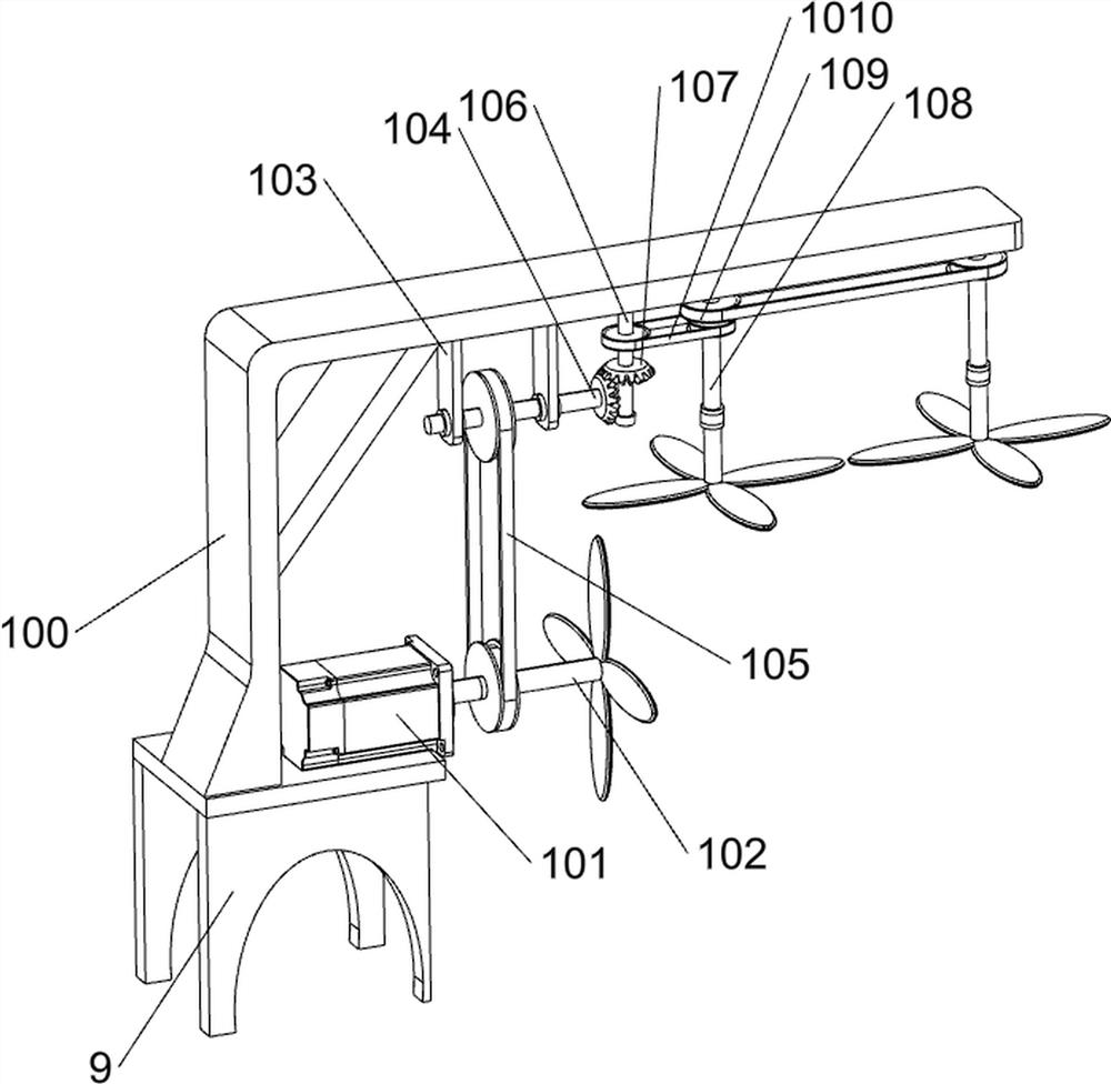
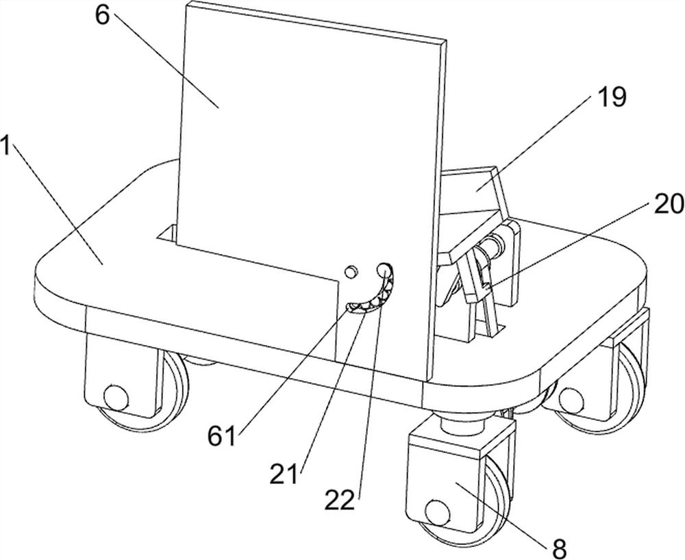
[0021]Automatic trimming equipment for garden seedlings, such asFigure 1-5As shown, including the bottom plate 1, the connecting plate 2, the first rotating shaft 3, the roller 4, the push hand 5, the support plate 6, the cleaning mechanism 7, the universal wheel 8, the stent 9, the trimming mechanism 10 and the storage box 23, the bottom plate 1 The rotation of the connecting plate 2 is provided in front of the lower right side, and the rotation type of the connecting plate 2 on both sides is provided with a first rotating shaft 3. The first rotating shaft 3 is provided with a roller 4, and the bottom plate 1 is provided on the right side of the upper right side. 5, the upper right side of the bottom plate 1 is provided with a support plate 6, and the support plate 6 opens a chute 61. The upper and rear symmetry rotation of the lower left side of the bottom plate 1 is provided with a mandrel wheel 8, and the bottom plate 1 is provided with a bracket 9. The upper port...
Example Embodiment
[0023]Example 2
[0024]On the basis of Example 1, such asfigure 2 withimage 3 The first bearing housing 70, the second axis 71, the first leather wheel assembly 72, the third rotating shaft 73, the first cone gear 74, the stationary frame 75, the second bearing housing 76, the fourth axis 77, conveyor belt 78, brush 79 and the second cone gear 710, the upper right front side of the bottom plate 1 is asymmetric, the first bearing housing 70 is provided, and the rotation type of the first bearing seat 70 on both sides is provided with the second axis 71, the second axis 71 and the first The connecting shaft 3 is connected to the first leather wheel assembly 72, and the upper right rear direction of the bottom plate 1 is provided with the third rotating shaft 73, and the third rotating shaft 73 and the second shaft 71 are provided with a first cone gear 74, two first cone gears. The upper portion of the support plate 6 is provided with a fixing frame 75, and the upper front and rear symm...
Example Embodiment
[0028]Example 3
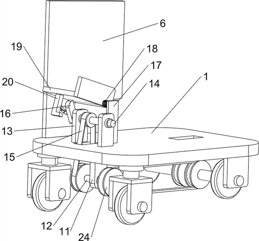
[0029]On the basis of Example 2, such asFigure 4 withFigure 5 The fourth bearing housing 11, the seventh axis 12, the fifth bearing housing 13, the eighth axle 14, the fifth leather wheel assembly 15, the rotating block 16, the support block 17, the torque spring assembly 18, the rotating member 19, the pull rod 20 The retracting spring 21, the slider 22, and the sixth leather wheel assembly 24, the lower left side of the bottom plate 1 is asymmetrically provided with the fourth bearing housing 11, and the strip of the fourth bearing housing 11 is provided with the seventh axis 12. The upper and rear of the upper left side of the bottom plate 1 is provided with the fifth bearing housing 13, and the rotating type of the fifth bearing housing 13 on both sides is provided with the eighth axle 14, and the eighth axis 14 and the seventh axis 12 are connected. The ribbon wheel assembly 15, the back side of the eighth rotating shaft 14 is provided with a rotary block 16, and...
PUM
 Abstract
Description
Claims
Application Information
 - R&D
- Intellectual Property
- Life Sciences
- Materials
- Tech Scout
- Unparalleled Data Quality
- Higher Quality Content
- 60% Fewer Hallucinations
Browse by: Latest US Patents, China's latest patents, Technical Efficacy Thesaurus, Application Domain, Technology Topic, Popular Technical Reports.
© 2025 PatSnap. All rights reserved.Legal|Privacy policy|Modern Slavery Act Transparency Statement|Sitemap|About US| Contact US: help@patsnap.com


