A suction mud scraper for environmental engineering

A technology of environmental protection engineering and mud scraper, which is applied to the feeding/discharging device, separation method, sedimentation separation and other directions of the settling tank, which can solve the problems of packing blockage and achieve the effect of convenient cleaning

Active Publication Date: 2022-04-05
建邦技术集团有限公司
View PDF18 Cites 0 Cited by
  • Summary
  • Abstract
  • Description
  • Claims
  • Application Information

AI Technical Summary

Problems solved by technology

[0005] In order to overcome the shortcomings of some improved sewage treatment processes, the sedimentation area and the biological reaction area are integrated, but the engineering of the inclined tube sedimentation tank is used in the sedimentation area, which is easy to cause serious plugging of fillers. The purpose of the present invention is to provide a Suction and scraper for environmental protection engineering that can facilitate sludge scraping and cleaning

Method used


Image

  • A suction mud scraper for environmental engineering
  • A suction mud scraper for environmental engineering
  • A suction mud scraper for environmental engineering

Examples


Embodiment 1

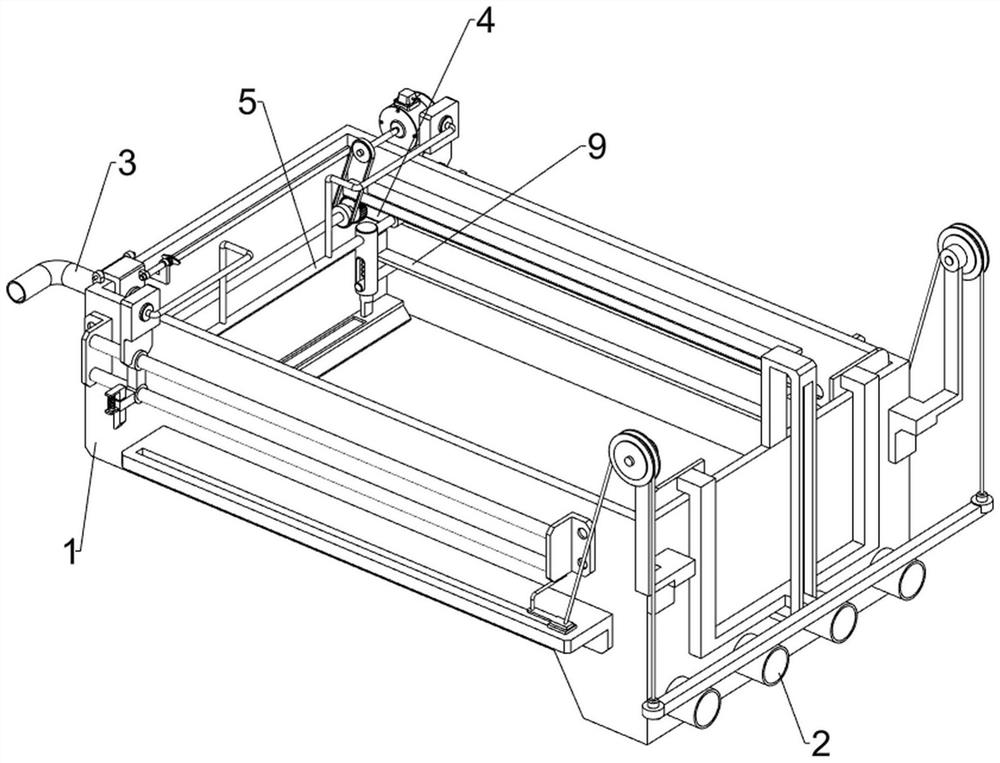
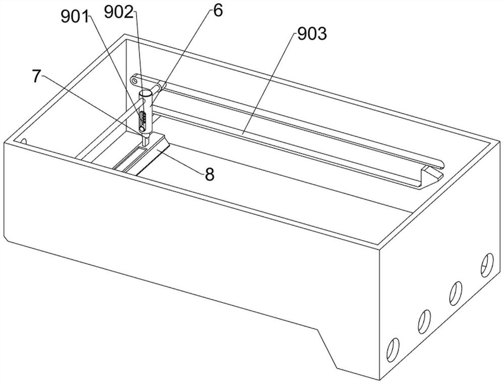
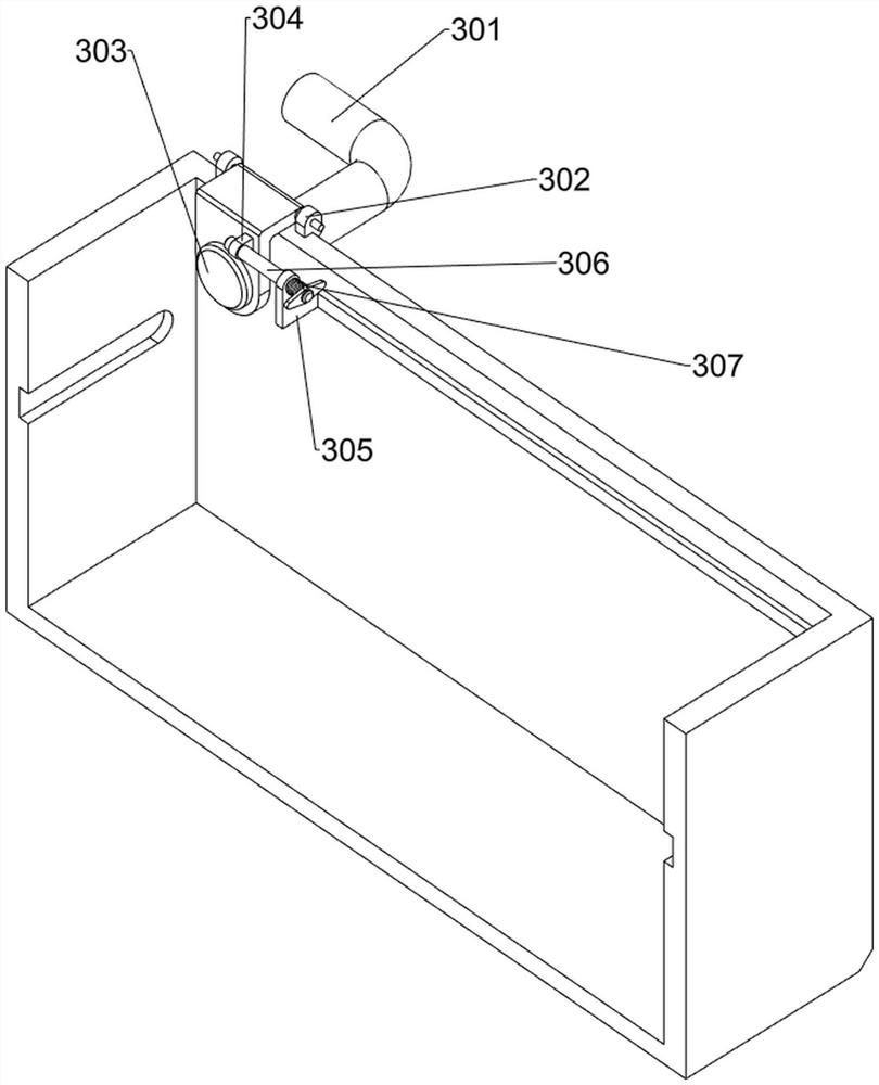
[0029] like figure 1 , figure 2 and image 3 As shown, a suction scraper for environmental protection engineering includes a sedimentation tank 1, a mud pump 2, a water inlet mechanism 3, a first slider 4, a first fixed rod 5, a first guide sleeve 6, and a guide rod 7. The mud scraper 8 and the reset mechanism 9, the right side of the sedimentation tank 1 is uniformly equipped with a mud pump 2, the mud pump 2 is connected through the lower side of the pipeline sedimentation tank 1, and the upper front side of the left side wall of the sedimentation tank 1 is provided with The water inlet mechanism 3, the front and rear inner walls of the sedimentation tank 1 are symmetrically opened with a word chute, the first slider 4 is slidably arranged on the inner side wall of the sedimentation tank 1, and the first slider 4 is arranged between the two first sliders 4 There is a first fixed rod 5, and the first fixed rod 5 is symmetrically embedded with a first guide sleeve 6, and a ...

Embodiment 2

[0034] Such as Figure 4 , Figure 5 , Image 6 , Figure 7 with Figure 8 As shown, on the basis of Embodiment 1, it also includes a first guide rod 10, a second slider 11, a third fixed rod 12, a first fixed block 13, a rack 14, a rotating shaft 15, a gear 16, a rotating Motor 17 and belt conveying device 18, settling box 1 both side walls are all symmetrically provided with two first guide rods 10, on the first guide rods 10 of both sides, all sliding type is provided with second slide block 11, the second slide block 11 and the first fixed rod 5 are provided with a third fixed rod 12, and the inner sidewalls of the sedimentation tank 1 are located above the special-shaped plate 903 and are provided with a first fixed block 13, and the bottom of the first fixed block 13 is provided with a rack 14. A rotating shaft 15 is rotatably arranged between the two first sliders 4, and a gear 16 is arranged at both ends of the rotating shaft 15, and the gear 16 meshes with the adj...


PUM


Abstract

The invention relates to a mud suction and scraper, in particular to a mud suction and scraper for environmental protection engineering. The invention provides a suction and scraper for environmental protection engineering which can facilitate sludge scraping and cleaning. The invention provides such a mud suction and scraper for environmental protection engineering, comprising: a sedimentation tank, a mud pump is uniformly arranged on the side of the sedimentation tank, and the mud pump is connected through the lower side of the sedimentation tank through a pipeline; a water inlet mechanism, a sedimentation tank A water inlet mechanism is arranged on the upper part of the side away from the dredging pump; the first slider and the inner side wall of the sedimentation tank are symmetrically opened with a slotted chute, and the slotted slots on the inner side wall of the sedimentation tank are all slidably provided with the first slider. The amount of water flowing into the sedimentation tank can be controlled by the water inlet mechanism. The staff will pull the first fixed rod to the right, and the first fixed rod will drive the first guide sleeve, guide rod and mud scraper to move to the right, and then the sludge deposited at the bottom will move to the right. The right side is scraped into the depression on the right side of the sedimentation tank, which is beneficial to the work of the dredge pump.

Description

technical field [0001] The invention relates to a mud suction and scraper, in particular to a mud suction and scraper for environmental protection engineering. Background technique [0002] With the development of society, the problem of shortage of water resources is becoming more and more serious, and water will become an important factor restricting social development. People are also paying more and more attention to the development and improvement of water treatment technology. [0003] The sewage biological treatment process is a special kind of sewage treatment process, also known as the activated sludge process. Activated sludge process can be divided into aerobic method and anaerobic method. At present, the widely used aerobic treatment process includes various forms such as AO, AAO, oxidation ditch, etc. The mud-water separation unit of most processes is separated from the biological treatment unit. Usually, the sludge in the aeration zone is discharged to the se...

Claims


Application Information

Patent Timeline
Patent Type & Authority Patents(China)
IPC IPC(8): B01D21/24B01D21/00
CPCB01D21/245B01D21/0006
Inventor 黄亮
Owner 建邦技术集团有限公司
Why Eureka
Try Eureka