
Bending and shaping die structure and bending process thereof

A technology for shaping punches and molds, which is applied in the field of bending and shaping mold structures and bending technology, and can solve problems such as sliders not being reset in time, stuck, stuck, etc.

Active Publication Date: 2021-04-30
厦门锐腾电子科技有限公司
View PDF7 Cites 0 Cited by
  • Summary
  • Abstract
  • Description
  • Claims
  • Application Information

AI Technical Summary

Problems solved by technology

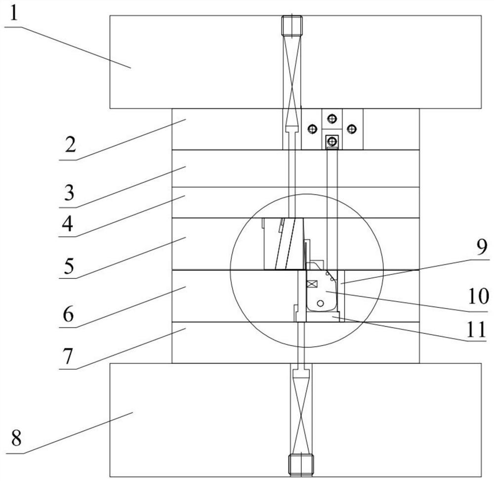
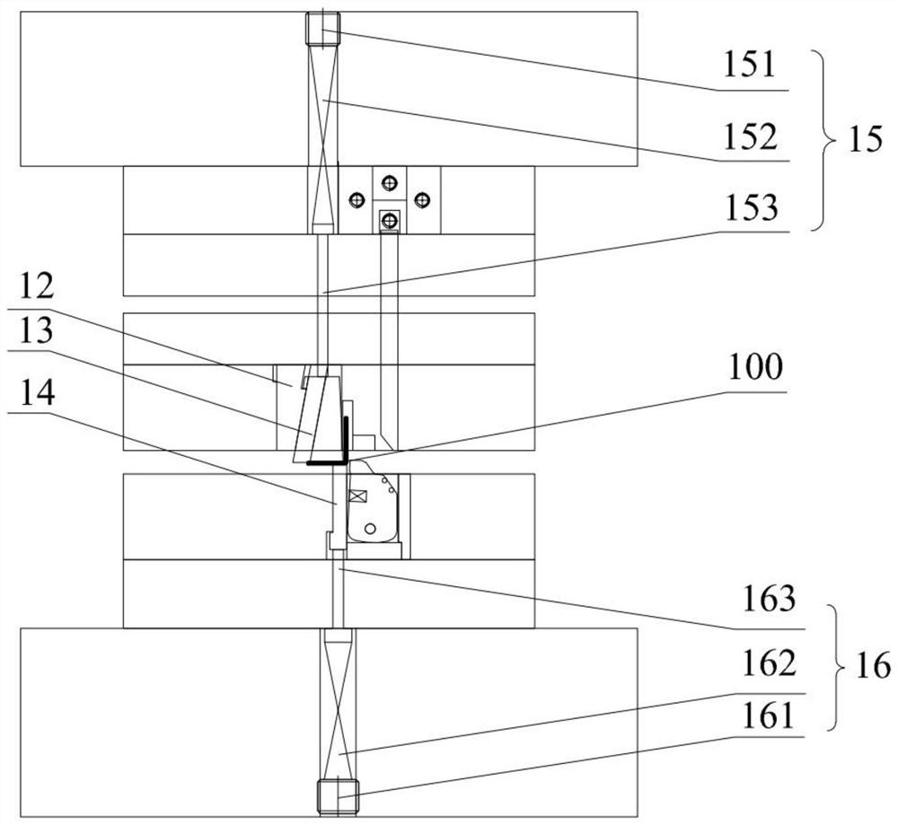
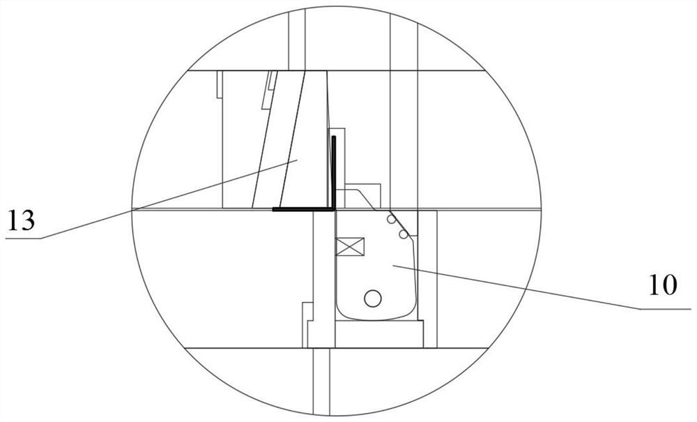
[0003] In view of the need for sliding fit between parts in the prior art, and the need to keep clean production at the same time, the plastic structure cannot be refueled during the mold loading and production process, so that after a long time of work, as the mold temperature rises, the powder in the mold Increased swarf, increased friction at the sliding position of parts, jamming, jamming, failure to reset the slider in time, reduced service life, and other uncontrollable risks to parts and molds, such as action failure, dimensional instability, etc. Problem, the present invention provides a bending and shaping mold structure, including a shaping punch, a movable block of a lower shaping die, and a fixed block of a lower shaping die, and the movable block of a lower shaping die is mounted on the fixed block of a lower shaping die through a rotating shaft , the shaping punch is located at a position above one side of the movable block of the lower shaping die, and the movable block of the lower shaping die is formed at a position directly below the shaping punch for contacting with the lower surface of the shaping punch. contact surface

Method used


Image

  • Bending and shaping die structure and bending process thereof
  • Bending and shaping die structure and bending process thereof
  • Bending and shaping die structure and bending process thereof

Examples


Embodiment Construction

[0049] In order to make the purpose, technical solutions and advantages of the embodiments of the present invention clearer, the technical solutions in the embodiments of the present invention will be clearly and completely described below in conjunction with the accompanying drawings in the embodiments of the present invention. Obviously, the described embodiments It is some embodiments of the present invention, but not all of them. Based on the implementation manners in the present invention, all other implementation manners obtained by persons of ordinary skill in the art without creative efforts fall within the protection scope of the present invention. Accordingly, the following detailed description of the embodiments of the invention provided in the accompanying drawings is not intended to limit the scope of the claimed invention, but merely represents selected embodiments of the invention. Based on the implementation manners in the present invention, all other implement...


PUM


Abstract

The invention discloses a bending and shaping die structure, and belongs to the field of shaping dies. The bending and shaping die structure comprises a shaping convex die, a shaping lower die movable block and a shaping lower die fixed block. The shaping lower die movable block is mounted on the shaping lower die fixed block through a rotating shaft, the shaping convex die is positioned at the position above one side of the shaping lower die movable block, and a contact face used for making contact with the lower surface of the shaping convex die is formed in the position, located under the shaping convex die, of the shaping lower die movable block. The bending and shaping die structure has the beneficial effects that, in the bending and shaping die structure, the shaping lower die movable block is mounted on the shaping lower die fixed block through the rotating shaft, compared with a conventional sliding structure, when the same effect is achieved, the friction effect is smaller, under the conditions that clean production is needed and oiling is not needed, friction force can be well reduced, the conditions of blocking and jamming and the condition that sliding blocks cannot reset in time are reduced, the service life of the die is prolonged, the product quality is ensured, and customer requirements are met.

Description

technical field [0001] The invention relates to the field of shaping molds, in particular to a bending shaping mold structure and a bending process thereof. Background technique [0002] In metal stamping dies, bending is a very common stamping process. In order to adjust the angle conveniently during the bending process, a plastic structure will be added in the mold to reduce the frequency of mold removal and repair. In order to reduce the cost of parts, parts that do not need post-process processing or cannot be processed in post-process are mostly used. In the actual production process, clean production is often used. Therefore, there is a higher requirement for the cleanliness of the mold. Due to the use of clean production, as far as possible without oil in the mold, it is easy to appear the phenomenon of slippery fit; the parts need to be slippery, and the mold needs clean production. No oil can be added during the mold loading and production process, and it will take...

Claims


Application Information

Patent Timeline
IPC IPC(8): B21D7/06
CPCB21D7/06
Inventor 陈哲李晨曦夏翰宇邓柳根
Owner 厦门锐腾电子科技有限公司
Learn More