Batch stamping and cutting device for metal plates

A technology of cutting device and metal plate, which is applied in the direction of cutting device with nibbling action, shearing device, accessory device of shearing machine, etc., can solve the problems of people injured and the quality of metal plate

Active Publication Date: 2021-04-30
合肥亿昌兴智能科技有限公司
View PDF7 Cites 3 Cited by
  • Summary
  • Abstract
  • Description
  • Claims
  • Application Information

AI Technical Summary

Problems solved by technology

[0005] The present invention overcomes that when people cut the metal plate with a hand-held cutting machine, the quality of the metal plate is likely to be affected to a certain extent due to manual operation errors, and when people directly contact the metal plate, the burrs on the metal plate are likely to make people Injured shortcomings, the technical problem to be solved by the present invention is to provide a metal plate batch punching and cutting device with high precision and efficiency for cutting metal plates and relatively safe manual operation

Method used


Image

  • Batch stamping and cutting device for metal plates
  • Batch stamping and cutting device for metal plates
  • Batch stamping and cutting device for metal plates

Examples


Embodiment 1

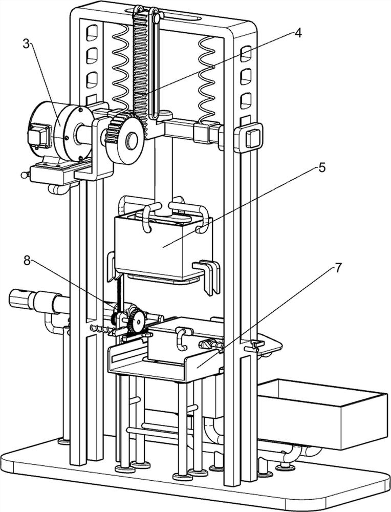
[0032] A batch stamping and cutting device for metal plates, such as Figure 1 to Figure 8 As shown, it includes a bottom plate 1, a mounting frame 2, a driving mechanism 3, a lifting mechanism 4, a punching mechanism 5, a top position mechanism 6, a feeding mechanism 7 and a transmission mechanism 8, and the rear side of the top of the bottom plate 1 is connected with a mounting frame 2 , the rear side of the middle part of the mounting frame 2 is connected with a driving mechanism 3, the rear side of the upper part of the mounting frame 2 is connected with a lifting mechanism 4, and the lifting mechanism 4 is connected with a punching mechanism 5, between the lower part of the mounting frame 2 and the punching mechanism 5 A jacking mechanism 6 is connected, a discharge mechanism 7 is connected to the rear side of the middle part of the bottom plate 1 , and a transmission mechanism 8 is connected between the right side of the top of the bottom plate 1 and the discharge mechani...

Embodiment 2

[0041] On the basis of Example 1, such as Figure 10 As shown, a discharge mechanism 10 is also included, and the discharge mechanism 10 includes a second fixed mount 101, a cylinder 102 and a second top block 103, and the front side of the bottom plate 1 top is connected with a second fixed mount 101, and the second fixed mount A cylinder 102 is connected to the top of the cylinder 101, and a second jacking block 103 is connected to the telescopic rod of the cylinder 102.

[0042] Also includes material receiving mechanism 11, and material receiving mechanism 11 includes inclined sliding frame 1101, the third fixed mount 1102, waste material receiving box 1103 and material receiving box 1104, the left side of discharging frame 73 is connected with inclined sliding frame 1101, bottom plate 1 The front side of the top is connected with a third fixed frame 1102, the third fixed frame 1102 is located at the rear side of the second fixed frame 101, the front side of the third fixe...

Embodiment 3

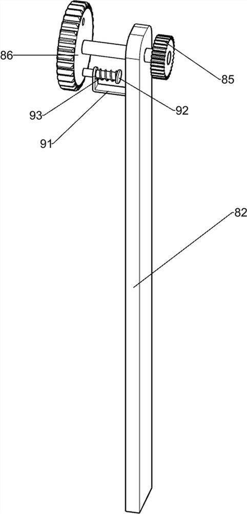
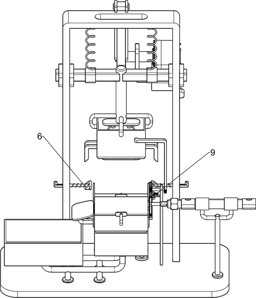
[0045] On the basis of Example 2, such as Figure 9 As shown, it also includes a locking mechanism 9. The locking mechanism 9 includes a fixed block 91, a guide post 92 and a tension spring 93. The left side of the upper part of the positioning plate 82 is connected with a fixed block 91, and the fixed block 91 is slidably connected. A guide post 92 is arranged, and the guide post 92 is matched with the groove, and a tension spring 93 is connected between the fixed block 91 and the guide post 92 .

[0046] Under the cooperation of the guide post 92 and the groove, when the cutter 52 cuts the metal plate, the transmission spur gear 86 and the third rack frame 84 maintain a certain stability, thereby indirectly making the discharge frame 73 and the metal plate The plate is more stable, which further improves the precision of cutting the metal plate.


PUM


Abstract

The invention relates to a stamping and cutting device, and particularly relates to a batch stamping and cutting device for metal plates. According to the batch stamping and cutting device for the metal plates, the cutting precision and the cutting efficiency of the metal plates are high, and manual operation is safe. The batch stamping and cutting device for the metal plates comprises a mounting frame connected to one side of a base plate; a driving mechanism connected to one side of the mounting frame; a lifting mechanism connected to the other side of the mounting frame; a blanking mechanism connected to the lifting mechanism; a jacking mechanism connected between the mounting frame and the blanking mechanism; a discharging mechanism connected to the other side of the base plate; and a conveying mechanism connected between the base plate and the discharging mechanism. The beneficial effects of the device are that under the effect of the driving mechanism, the lifting mechanism, the blanking mechanism, the jacking mechanism, the discharging mechanism and the conveying mechanism, people can continuously and accurately cut the metal plates.

Description

technical field [0001] The invention relates to a punching and cutting device, in particular to a batch punching and cutting device for metal plates. Background technique [0002] In the production process of metal objects, the parts of some objects have certain specifications and ratio requirements, and people need to cut the metal plates to form corresponding specifications in order to meet the production requirements. At present, the price of stamping and cutting devices for metal plates on the market is generally higher Expensive, and the production cost is high, so many people now use manual hand-held cutting machines to cut metal plates. Such an operation may easily lead to a certain deviation in the specification ratio of the metal plate cutting due to manual errors, and it is not necessary Suitable for cutting large quantities of metal plates. [0003] Therefore, urgently need to design a kind of cutting precision and efficiency higher to metal plate, manual operati...

Claims


Application Information

Patent Timeline
Patent Type & Authority Applications(China)
IPC IPC(8): B23D27/00B23D33/02B23Q5/34B23Q11/00
CPCB23D27/00B23D33/02B23Q5/34B23Q11/0042
Inventor 李志克
Owner 合肥亿昌兴智能科技有限公司
Why Eureka
Try Eureka