
Push-type polishing mechanism based on medical sliding block

A polishing mechanism and push-type technology, applied in surface polishing machine tools, grinding/polishing equipment, grinding racks, etc., can solve the problems of reduced cylindricity and difficulty in ensuring the same degree of cylindrical surface polishing of parts.

Active Publication Date: 2021-04-30
XUZHOU SHENFENG PRECISION MASCH CO LTD
View PDF5 Cites 1 Cited by
  • Summary
  • Abstract
  • Description
  • Claims
  • Application Information

AI Technical Summary

Problems solved by technology

[0002] Medical equipment needs to be maintained during use. When polishing and maintaining parts, push-type polishing is often used, that is, the parts are pushed into the grinding disc through the slider to move and polish. However, when polishing cylindrical parts, it is difficult to ensure the cylindricality of the parts. The polishing degree of the surface is the same, which often results in a large amount of grinding on one side and a small amount on the other side, resulting in a decrease in the cylindricity of the part after polishing. For this reason, we propose a medical slider-based polishing mechanism to solve the above problems

Method used


Image

  • Push-type polishing mechanism based on medical sliding block
  • Push-type polishing mechanism based on medical sliding block
  • Push-type polishing mechanism based on medical sliding block

Examples


Embodiment Construction

[0022] The following will clearly and completely describe the technical solutions in the embodiments of the present invention with reference to the accompanying drawings in the embodiments of the present invention. Obviously, the described embodiments are only some, not all, embodiments of the present invention. Based on the embodiments of the present invention, all other embodiments obtained by persons of ordinary skill in the art without making creative efforts belong to the protection scope of the present invention.

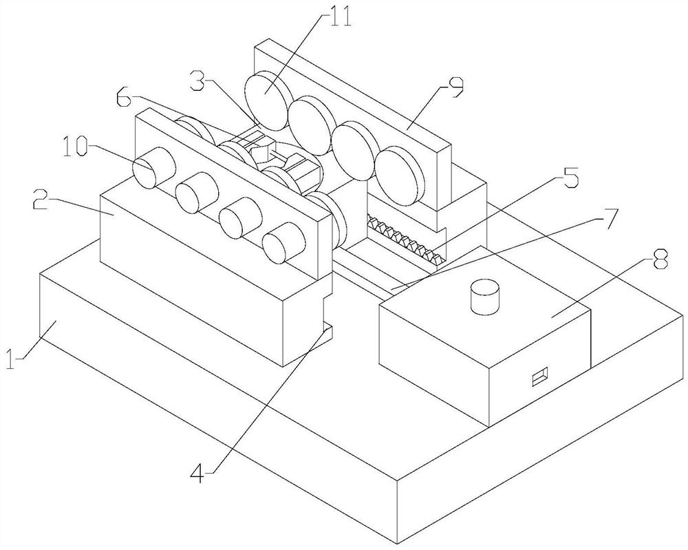
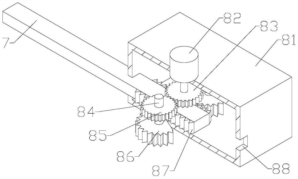
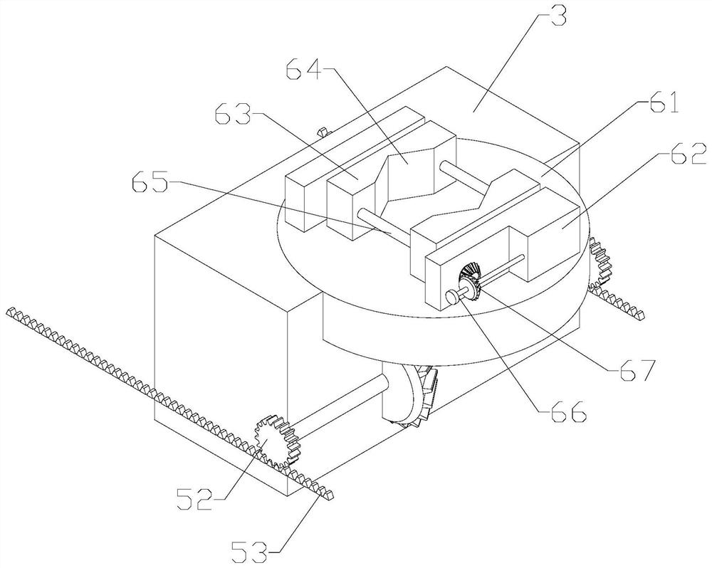
[0023] see Figure 1-4 , the present invention provides a technical solution: a push-type polishing mechanism based on medical sliders, including a base 1, one end of the base 1 is fixedly installed with a guide plate 2, the guide plate 2 slides and engages with the slider 3, and the guide plate 2 is close to the slide One side of the block 3 is provided with a guide groove 4, a rotating mechanism 5 is installed between the slide block 3 and the guide groove 4...


PUM


Abstract

The invention discloses a push-type polishing mechanism based on a medical sliding block. The push-type polishing mechanism comprises a base, guide plates are fixedly mounted at one end of the base, the sliding block is clamped between the guide plates, a guide groove formed in one side of each guide plate, a rotating mechanism is mounted between the sliding block and the guide grooves, a positioning mechanism is mounted on the sliding block, the rotating mechanism is connected with the positioning mechanisms, and a push rod is connected to one side of the sliding block, a driving mechanism is installed at the top of the base, the push rod is connected with the driving mechanism, vertical plates are installed at the tops of the guide plates, polishing motors are fixedly installed on the outer wall of one vertical plate, and output shafts of the polishing motors rotationally penetrate through the vertical plates and are fixedly provided with polishing discs. Parts are positioned and clamped on the sliding block through the positioning mechanism, the driving mechanism drives the push rod to reciprocate at a constant speed, the push rod pushes the sliding block to slide between the guide plates, the sliding block drives the parts to rotate through the rotating mechanism during sliding, and when the polishing motors drive the polishing discs to polish the outer walls of the parts, the parts are kept in a reciprocating rotating state, and polishing is more uniform, and the surface cylindricity of polished cylindrical parts is kept unchanged.

Description

technical field [0001] The invention relates to the technical field of medical device polishing, in particular to a medical slider-based push-type polishing mechanism. Background technique [0002] Medical equipment needs to be maintained during use. When polishing and maintaining parts, push-type polishing is often used, that is, the parts are pushed into the grinding disc through the slider to move and polish. However, when polishing cylindrical parts, it is difficult to ensure the cylindricality of the parts. The polishing degree of the surface is the same, which often results in a large amount of grinding on one side and a small amount on the other side, resulting in a decrease in the cylindricity of the part after polishing. For this reason, we propose a medical slider-based polishing mechanism to solve the above problems. Contents of the invention [0003] The purpose of the present invention is to provide a medical slider-based push-type polishing mechanism to solve...

Claims


Application Information

Patent Timeline
IPC IPC(8): B24B29/04B24B5/04B24B5/36B24B41/02B24B41/06B24B47/12
CPCB24B29/04B24B5/047B24B5/363B24B41/02B24B41/067B24B47/12
Inventor 丁后璧
Owner XUZHOU SHENFENG PRECISION MASCH CO LTD
Learn More