Wafer rotating chuck optimized on basis of cathode spray head position change

A technology for rotating chucks and wafers, applied in electrical components, work carriers, metal processing equipment, etc., can solve problems such as uneven polishing, and achieve the effect of improving polishing uniformity and effect

Active Publication Date: 2017-01-25
ACM RES SHANGHAI
View PDF8 Cites 0 Cited by
  • Summary
  • Abstract
  • Description
  • Claims
  • Application Information

AI Technical Summary

Problems solved by technology

When the cathode nozzle moves to the plastic ring on the edge of the wafer, the area where it intersects with the wafer will gradually decrease as the distance increases. If the same polishing current is used, the effective polishing current density will inevitably increase, resulting in uneven polishing

Method used


Image

  • Wafer rotating chuck optimized on basis of cathode spray head position change
  • Wafer rotating chuck optimized on basis of cathode spray head position change
  • Wafer rotating chuck optimized on basis of cathode spray head position change

Examples


Embodiment Construction

[0021] The above-mentioned features and advantages of the present invention can be better understood after reading the detailed description of the embodiments of the present disclosure in conjunction with the following drawings. In the drawings, components are not necessarily drawn to scale, and components with similar related properties or characteristics may have the same or similar reference numerals.

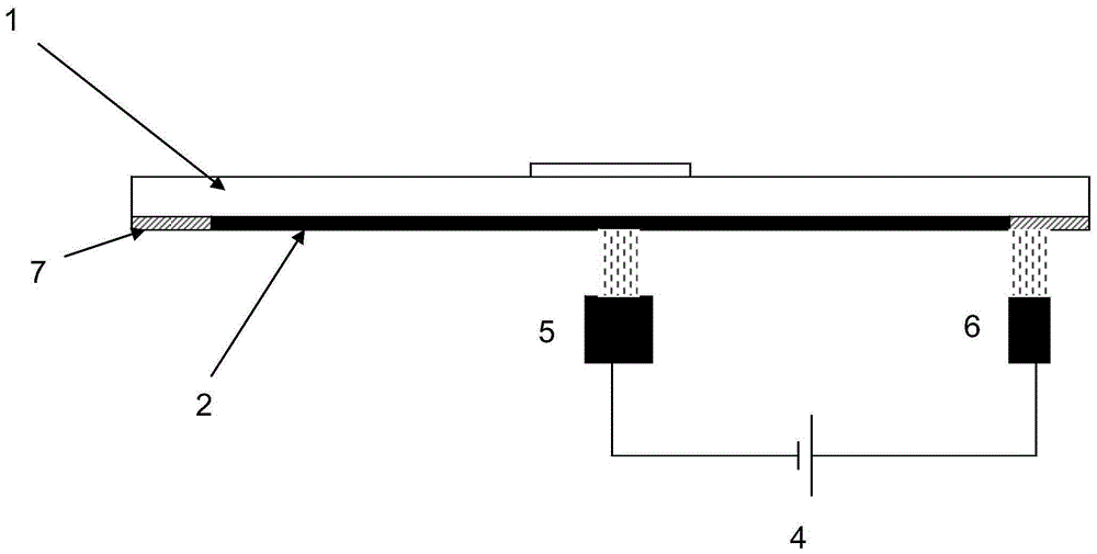
[0022] figure 1 A schematic diagram showing a wafer spin chuck in a stress-free polishing process. figure 2 A schematic diagram showing the starting position of the cathode shower head movement in the preferred embodiment of the wafer spin chuck optimized based on the position change of the cathode shower head of the present invention. image 3 A schematic diagram showing the termination position of the cathode showerhead movement in the preferred embodiment of the wafer spin chuck. Figure 4 A schematic diagram showing the cathode shower head moving to the edge of the wa...


PUM


Abstract

The invention discloses a wafer rotating chuck optimized on the basis of cathode spray head position change. A polishing current is regulated on the basis of position change in the cathode spray head moving process, and then the purpose of uniform polishing is achieved. According to the technical scheme, the radius of the chuck is larger than that of a wafer, a circular ring is arranged on the portion, exceeding the wafer, of the chuck, a wafer slot is formed in the middle of the chuck and used for adsorbing the wafer, and a power supply, a cathode spray head and an anode spray head are arranged below the chuck; the position of the anode spray head is constant relative to the wafer, the cathode spray head moves to the circular ring outside the wafer from the center of the wafer along the radius of the wafer, when the cathode spray head moves to the edge of the wafer, the intersection area of the cathode spray head and the wafer is decreased along with movement, and the polishing current on the cathode spray head is correspondingly decreased.

Description

technical field [0001] The invention relates to a wafer rotary chuck in a stress-free polishing process, in particular to a wafer rotary chuck that optimizes the polishing effect based on the change of the position of the cathode nozzle. Background technique [0002] In the traditional stress-free polishing SFP process, the connection between the positive and negative poles of the power supply and the wafer is realized through the polishing liquid joint, and the two-stage connected polishing liquid is ejected from the cathode nozzle and the anode nozzle respectively. During the process, it moves relative to the chuck in the horizontal direction. When the cathode nozzle moves to the plastic ring on the edge of the wafer, the area where it intersects with the wafer will gradually decrease as the distance increases. If the same polishing current is used, the effective polishing current density will inevitably increase, resulting in Uneven polishing. Contents of the invention...

Claims


Application Information

Patent Timeline
Patent Type & Authority Applications(China)
IPC IPC(8): B24B37/30B24B57/02H01L21/683
CPCB24B37/30B24B57/02H01L21/683
Inventor 代迎伟金一诺王坚王晖
Owner ACM RES SHANGHAI
Why Eureka
Try Eureka