Aviation aircraft winglet

An aircraft and wingtip technology, applied in the field of aviation aircraft winglets, can solve the problems of changing winglets and not being able to switch flight speeds, and achieve precise transmission accuracy, improved drag reduction effect, and precise glide distance

Active Publication Date: 2021-04-30
江西经济管理干部学院
View PDF20 Cites 0 Cited by
  • Summary
  • Abstract
  • Description
  • Claims
  • Application Information

AI Technical Summary

Problems solved by technology

[0004] Most of the existing winglets adopt the design of fixed chord length, and the chord length of the winglet cannot be switched according to the flight speed of the aircraft.

Method used


Image

  • Aviation aircraft winglet
  • Aviation aircraft winglet
  • Aviation aircraft winglet

Examples


Embodiment 1

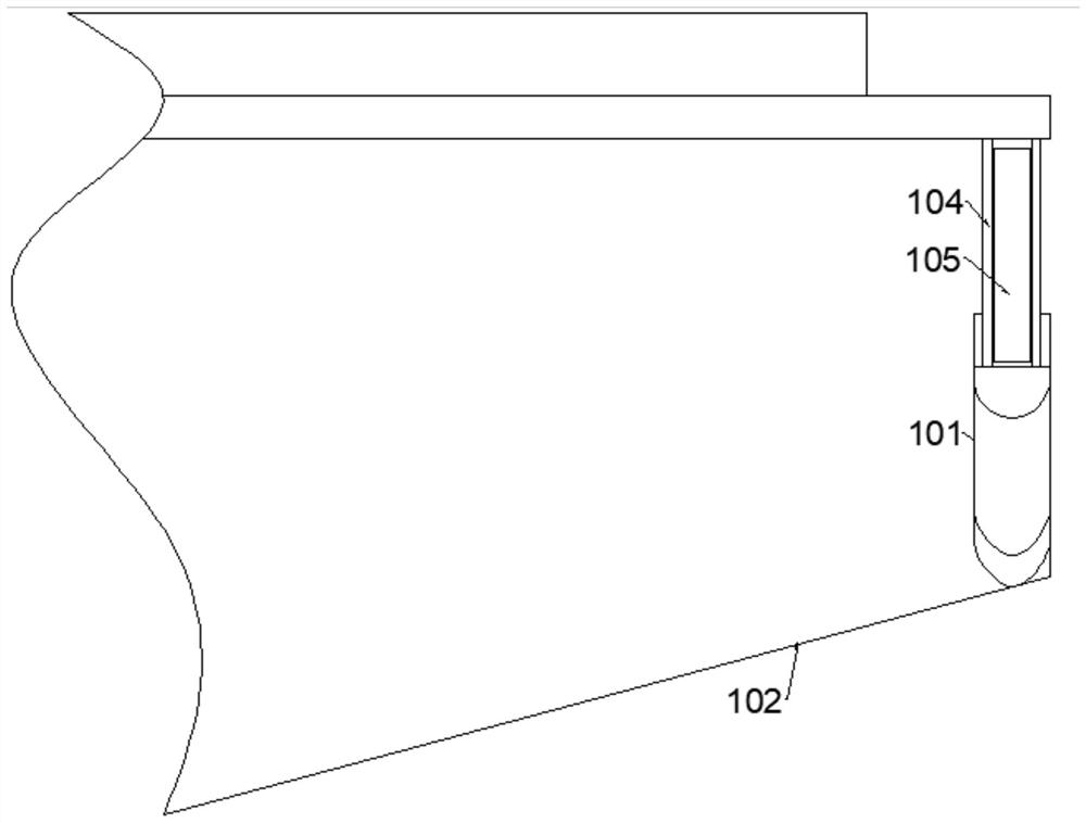
[0025] Such as Figure 1-3 As shown, a kind of aviation aircraft winglet provided by the present invention comprises: sliding wing 101, telescopic wing and transmission device, and sliding wing 101 is slidably connected to the upper surface wingtip place of aircraft main wing 102, and described sliding wing 101 can The wing tip on the upper surface of the main wing 102 of the aircraft slides axially along the fuselage of the aircraft. The sliding wing 101 is provided with a first chamber 103; the telescopic wing can be accommodated in the first chamber 103. 105, the outer wall of the outer wing 104 is slidably connected with the first chamber 103, the outer wing 104 is provided with a second chamber 106, the outer wall of the inner wing 105 is slidably connected with the second chamber 106, and the inner wing 105 can extend out of the outer wing 104 , the outer wing 104 is fixedly connected to the rear half of the wingtip on the upper surface of the main wing 102 of the aircra...

Embodiment 2

[0031] On the basis of Embodiment 1, in order to enable the sliding wing 101 to slide along the axial direction of the fuselage, the telescopic wing can automatically expand and contract.

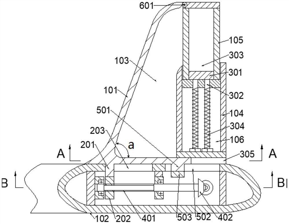
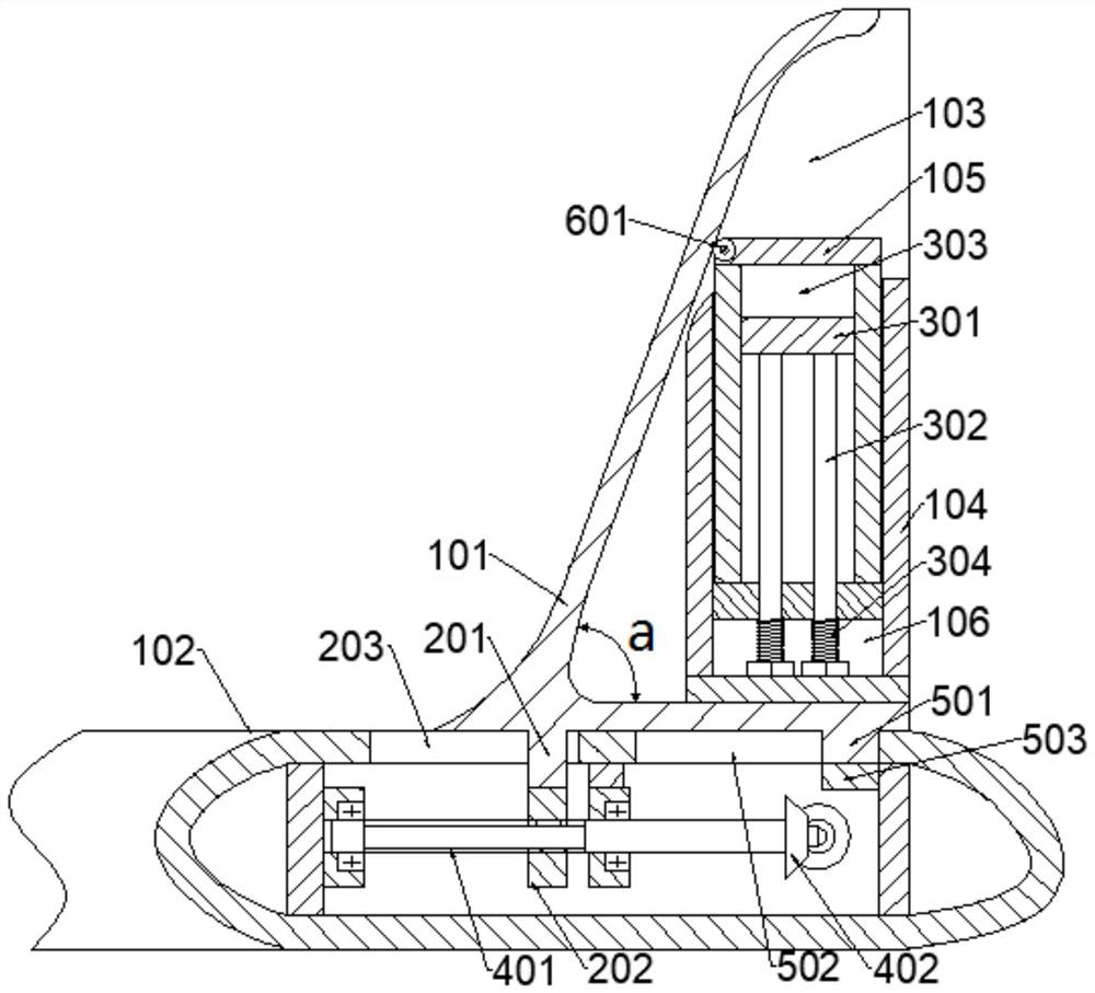
[0032] Such as figure 2 , 3 and 5, wherein, the bottom wall of the sliding wing 101 is slidingly connected with the upper surface of the aircraft main wing 102, the bottom wall of the sliding wing 101 is provided with a first slider 201, and one end of the first slider 201 is fixedly connected to the sliding wing 101 Bottom wall, the other end of the first slider 201 is fixedly connected with a screw nut sleeve 202, and the upper surface of the aircraft main wing 102 is provided with a first through groove 203 at the tip of the wing, and the first slider 201 is slidably connected with the first through groove 203 , the screw nut sleeve 202 is connected with the transmission device.

[0033] Such as figure 2 and 3 As shown, wherein, the telescopic wing also includes a first stopper 301...


PUM


Abstract

The invention discloses an aviation aircraft winglet, and belongs to the technical field of aviation equipment. Theaviation aircraft winglet comprises a sliding wing which is slidably connected to the wingtip of the upper surface of an aircraft main wing, can slide in the axial direction of an aircraft body at the wingtip of the upper surface of the aircraft main wing, and is internally provided with a first cavity, a telescopic wing that can be contained in the first cavity, comprises an outer wing having the outer wallslidably connected with the first cavity and being provided with a second cavity and an inner wing, and a transmission device arranged in the aircraft main wing, connected with the sliding wing and used for providing power for sliding of the sliding wing, and connected with a power device. According to the aviation aircraft winglet, the chord length of the winglet can be changed according to the flight speed of an aircraft, and when the aircraft flies at a low speed, the drag reduction effect of the winglet is improved. When the aircraft flies at a high speed, adverse interference caused by superposition of high-speed airflow on the inner surface of the winglet and high-speed airflow on the front section of the upper surface of the wing is avoided.

Description

technical field [0001] The invention relates to the technical field of aviation equipment, in particular to an aviation aircraft winglet. Background technique [0002] The winglets can function as end plates, increasing the effective aspect ratio of the wing. Secondly, when the winglet generates lift, it also produces a strong wake vortex that crosses the wingtip wake vortex, which weakens and dissipates the wingtip vortex, thereby reducing the induced drag. Therefore, most modern military transport aircraft and civilian airliners are equipped with winglets. [0003] When the aircraft is flying at low speed, the winglet adopts a larger chord length, which can improve the drag reduction effect of the winglet. When the aircraft flies at high speed, the winglet adopts a smaller chord length and is arranged on the rear half of the upper surface of the wing tip, which can avoid adverse interference caused by the superposition of the high-speed airflow on the inner surface of th...

Claims


Application Information

Patent Timeline
Patent Type & Authority Applications(China)
IPC IPC(8): B64C3/38B64C23/06
CPCB64C3/38B64C23/065Y02T50/10
Inventor 徐剑锋
Owner 江西经济管理干部学院
Why Eureka
Try Eureka