Deviation rectifying mechanism and deviation rectifying device

A technology of deviation correction device and drive motor, which is applied in transportation and packaging, winding strips, thin material processing, etc., and can solve problems such as film material transmission deviation

Pending Publication Date: 2021-04-30
BEIJING SEMICON EQUIP INST THE 45TH RES INST OF CETC
View PDF0 Cites 0 Cited by
  • Summary
  • Abstract
  • Description
  • Claims
  • Application Information

AI Technical Summary

Problems solved by technology

[0004] The purpose of the present invention is to provide a deviation correction mechanism and deviation correction device,

Method used


Image

  • Deviation rectifying mechanism and deviation rectifying device
  • Deviation rectifying mechanism and deviation rectifying device

Examples


no. 1 example

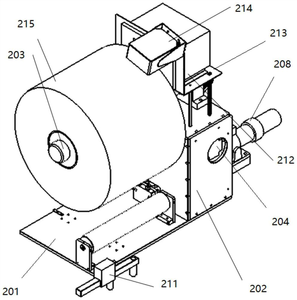
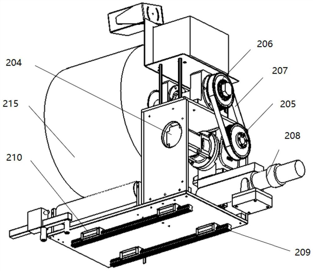
[0038] Please refer to figure 1 and figure 2 , this embodiment provides a deviation correction mechanism, which includes a material rack, a first drive assembly, a second drive assembly, and a guide assembly;

[0039] The material frame includes a bottom support plate 201, a material roll support frame 202 and a film roll-out shaft 203; the material roll support frame 202 is arranged on one side of the bottom support plate 201; the film roll-out shaft 203 and the film roll-out shaft 203 The first driving assembly is respectively fixed on the material roll supporting frame 202, the film unwinding shaft 203 is used to wind the material roll 215, and the first driving assembly is used to drive the film unwinding shaft 203 to rotate, so as to Realize the feeding or receiving of material roll 215;

[0040]The output end of the second driving assembly is connected to the material rack, and is used to drive the material rack to move in a direction parallel to the film unwinding sh...

no. 2 example

[0052] This embodiment provides a deviation correction device, which includes a control assembly, and the deviation correction mechanism in the first embodiment;

[0053] The control assembly is electrically connected with the deviation correction mechanism, and is used to control the operation of the first drive assembly and the second drive assembly.

[0054] The deviation correction device of this embodiment includes a control assembly, the first drive assembly and the second drive assembly are electrically connected to the control assembly, under the control of the control assembly, the first drive assembly drives the film unwinding shaft 203 to move, and the second drive assembly Drive the rack to move.

[0055] In the above technical solution, further, the control component includes an edge finding sensor 211 and a deviation correction controller 212;

[0056] The edge finding sensor 211 is electrically connected to the deviation correction controller 212;

[0057] The...


PUM


Abstract

The invention provides a deviation rectifying mechanism and a deviation rectifying device, and relates to the technical field of laminating devices. The deviation rectifying mechanism comprises a material frame, a first driving assembly, a second driving assembly and a guiding assembly; the material frame comprises a bottom supporting plate, a material roll supporting frame and a diaphragm rolling-out shaft; the material roll supporting frame is arranged on one side of the bottom supporting plate; the diaphragm rolling-out shaft and the first driving assembly are fixed to the material roll supporting frame, the diaphragm rolling-out shaft is used for winding a material roll, and the first driving assembly is used for driving the diaphragm rolling-out shaft to rotate so as to achieve feeding or receiving of the material roll; the output end of the second driving assembly is connected with the material frame, and the second driving assembly is used for driving the material frame to move in the direction parallel to the diaphragm rolling-out shaft; and the guiding assembly is arranged below the bottom supporting plate and used for guiding movement of the material frame. The deviation rectifying mechanism and the deviation rectifying device solve the problem of deviation of diaphragm materials in the conveying process, and therefore, the production efficiency is improved.

Description

technical field [0001] The invention relates to the technical field of lamination devices, in particular to a deviation correction mechanism and a deviation correction device. Background technique [0002] Chip ceramic capacitors have the advantages of small size, low internal inductance, high insulation resistance, small leakage current, low dielectric loss, and low price. They are widely used in oscillation, coupling, filtering, and bypass circuits in various electronic machines. Especially high frequency circuits. Compared with other capacitors, MLCC is especially suitable for chip surface assembly, which can greatly increase the circuit assembly density and reduce the volume of the whole machine. This outstanding feature makes chip MLCC the largest and fastest growing type in the world. chip components. [0003] In the stacking device of chip ceramic capacitors, the blank ceramic diaphragm rolls are transported to the stripping station through the transmission mechanis...

Claims


Application Information

Patent Timeline
IPC IPC(8): B65H18/02B65H18/14B65H23/032B65H26/00
CPCB65H18/026B65H18/14B65H23/0328B65H26/00B65H2701/10
Inventor 乔文远邓珏琼朱林涛
Owner BEIJING SEMICON EQUIP INST THE 45TH RES INST OF CETC
Why Eureka
Try Eureka