Counterweight assembly for hoisting equipment and hoisting equipment

A technology of lifting equipment and counterweight assembly, which is applied in the directions of cranes, load hanging components, transportation and packaging, etc. It can solve the problems of increased equipment working space requirements, manufacturing weight, and non-adjustable center of gravity, and achieves manufacturing costs and The use of equipment is economical in energy consumption, manufacturing and use costs are economical, and the effect of reducing equipment weight

Active Publication Date: 2021-04-30
湖南中铁五新重工有限公司
View PDF8 Cites 0 Cited by
  • Summary
  • Abstract
  • Description
  • Claims
  • Application Information

AI Technical Summary

Problems solved by technology

[0004] The center of gravity fixedly installed on the tail assembly of the vehicle frame cannot be adjusted. The disadvantage is that the upper counterweight needs to be made heavier to balance the lifting moment of the equipment, which increases the manufacturing cost of the equipment. and energy consumption
In fact, the disadvantages of the upper counterweight, which is installed on the tail assembly of the vehicle frame with an adjustable center of gravity, are as follows: 1. The center of gravity of the counterweight is close to the cab side of the equipment, and the movement and adjustment range of the counterweight is relatively large. (The distance that the counterweight protrudes from the tail assembly of the frame should be longer) or the counterweight is heavier
2. Because the distance that the counterweight protrudes from the tail assembly of the frame is too long, the overall length of the equipment will be increased, and the requirements for the working space of the equipment will be increased, which will limit the use of the equipment and make it difficult to generalize
[0006] The rear counterweight is basically fixed on the rear side of the frame tail assembly at present, and the center of gravity cannot be adjusted. The disadvantage is that the upper counterweight also needs to be made relatively large to balance the lifting moment of the equipment. Heavy, which increases the manufacturing cost and energy consumption of the equipment

Method used


Image

  • Counterweight assembly for hoisting equipment and hoisting equipment
  • Counterweight assembly for hoisting equipment and hoisting equipment
  • Counterweight assembly for hoisting equipment and hoisting equipment

Examples


Embodiment

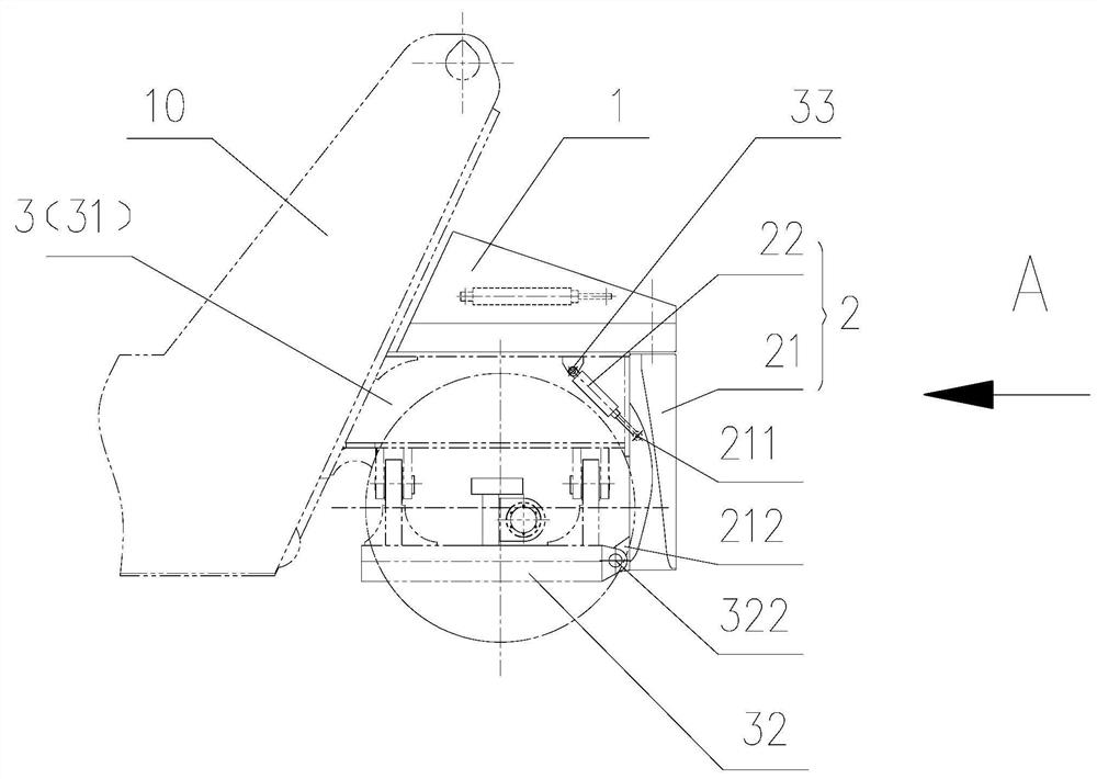
[0037] Mobile lifting equipment such as a container reach stacker generally includes a vehicle frame 10 and a jib. The rear of the vehicle frame 10 has a vehicle frame tail assembly 3. The tail of the jib is installed on the vehicle There is a lifting mechanism. Container front stacker cranes generally use counterweights to balance the lifting moment.

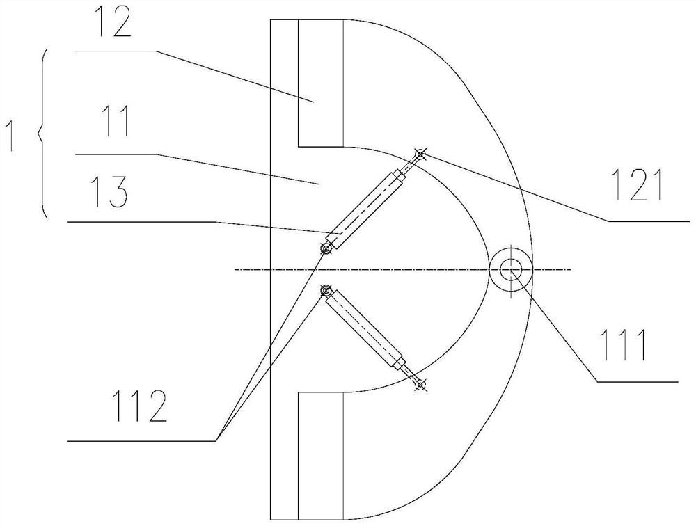
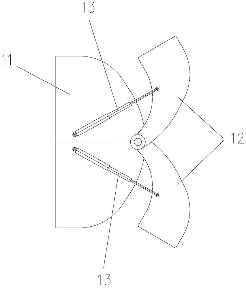
[0038] Such as Figure 1-Figure 5 As shown, the counterweight assembly for lifting equipment in this embodiment includes an upper counterweight assembly 1 located at the upper end of the lifting equipment frame tail assembly 3, and an upper counterweight assembly 1 located at the lifting equipment frame tail assembly. 3 Rear counterweight assembly 2 at the rear end.

[0039] Wherein, the upper counterweight assembly 1 includes a fixed block 11 , two adjusting blocks 12 and two first driving members 13 corresponding to the adjusting blocks 12 one-to-one. The fixed block 11 is detachably installed on the upper end panel 31 of ...


PUM


Abstract

The invention discloses a counterweight assembly for hoisting equipment and the hoisting equipment. The counterweight assembly comprises an upper counterweight assembly arranged at the upper end of a frame tail assembly of the hoisting equipment and a rear counterweight assembly arranged at the rear end of the frame tail assembly of the hoisting equipment. The upper counterweight assembly comprises an adjusting block and a first driving piece for driving the adjusting block to rotate in the horizontal plane, one end of the adjusting block is hinged to the frame tail assembly, and the first driving piece drives the adjusting block to rotate so that the other end of the adjusting block can turn to the rear side of the frame tail assembly. The rear counterweight assembly comprises a rear balance weight and a second driving piece for driving the rear balance weight to rotate in the vertical plane, one end of the rear balance weight is hinged to the frame tail assembly, and the second driving piece drives the rear balance weight to rotate so that the other end of the rear balance weight can be far away from the frame tail assembly. Through rotation of the upper counterweight assembly and the rear counterweight assembly, the purpose of adjusting the gravity center of the equipment is achieved, the gravity center of the equipment can be adjusted within a larger range through rotation within a smaller range, and the overall stability is better.

Description

technical field [0001] The invention relates to the technical field of hoisting equipment, in particular to a counterweight assembly for hoisting equipment and the hoisting equipment. Background technique [0002] Mobile lifting equipment such as container reach stacker cranes generally balance the lifting moment through counterweights. At present, the counterweight of mobile lifting equipment such as container reach stacker cranes consists of an upper counterweight and a rear counterweight. [0003] The upper counterweight is set on the rear assembly of the frame. In order to facilitate the observation of the rear view in the equipment cab when the equipment is in use, its overall structure is such that the center of gravity of the upper counterweight is close to the side of the equipment cab, that is, the upper The external dimension of the cab side of the counterweight near the equipment is larger than that of the rear of the equipment. At present, there are mainly two s...

Claims


Application Information

Patent Timeline
Patent Type & Authority Applications(China)
IPC IPC(8): B66C23/72B66C13/00
CPCB66C23/72B66C13/00
Inventor 任军辉张桂张维友祁加勇袁光金
Owner 湖南中铁五新重工有限公司
Why Eureka
Try Eureka