Transmission gear shifting and parking structure and new energy automobile

A transmission and parking technology, applied in the direction of instruments, controlled components, mechanical control devices, etc., can solve problems such as inability to meet space layout requirements, and achieve the effects of saving layout space, reducing the number of parts and reducing costs

Pending Publication Date: 2021-04-30
JING JIN ELECTRIC TECH CO LTD
View PDF0 Cites 1 Cited by
  • Summary
  • Abstract
  • Description
  • Claims
  • Application Information

AI Technical Summary

Problems solved by technology

In the field of new energy vehicles where the integration of power systems is getting higher and higher, the integration of various systems is getting higher and higher, and the traditional layout can no longer meet the space layout requirements.

Method used


Image

  • Transmission gear shifting and parking structure and new energy automobile
  • Transmission gear shifting and parking structure and new energy automobile
  • Transmission gear shifting and parking structure and new energy automobile

Examples


Embodiment 1

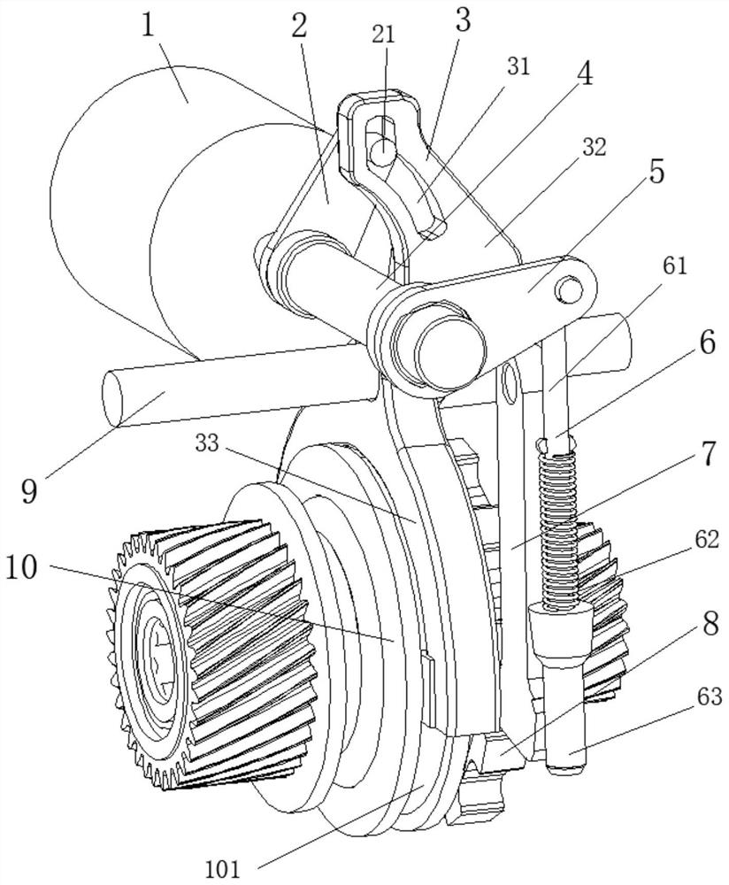
[0032] according to figure 1 The schematic diagram of the shifting and parking structure shown, the transmission shifting and parking structure includes a rotary drive mechanism 1, a shifting arm 2, a shift fork 3, a shifting actuator, a drive guide shaft 4, and a parking arm 5 And the parking push rod assembly 6 and the parking actuator, wherein the rotary drive mechanism 1 is preferably a motor; the rotary drive mechanism 1 is used to drive the rotation of the drive guide shaft 4; one end of the shift arm 2 and the One end of the parking arm 5 is fixed, such as welded, on the driving guide shaft 4 and rotates with the driving guide shaft 4 .

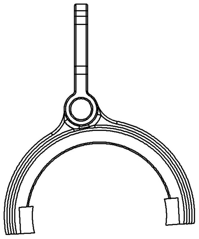
[0033] The other end of the shifting arm 2 is provided with a cylindrical pin 21, and the cylindrical pin 21 moves along the fork-shaped wire groove 31 provided on the shifting fork 3 with the rotation of the shifting arm 2 and drives the The shift fork 3 moves, as shown in Fig. 3(a)-(d), the shift fork type wire groove 31 is provided...

Embodiment 2

[0043] Embodiment 2 discloses a new energy vehicle, which adopts the shifting and parking structure in Embodiment 1. It should be noted that the reversing of the new energy vehicle is realized by reversing the main motor.


PUM


Abstract

The invention discloses a transmission gear shifting and parking structure and a new energy automobile. The transmission gear shifting and parking structure comprises a rotary driving mechanism, a gear shifting rotary arm, a shifting fork, a gear shifting executing mechanism, a driving guide shaft, a parking rotary arm, a parking push rod assembly and a parking executing mechanism; the rotary driving mechanism is used for driving the driving guide shaft to rotate; one end of the gear shifting rotary arm and one end of the parking rotary arm are fixed to the driving guide shaft and rotate along with the driving guide shaft; a cylindrical pin is arranged at the other end of the gear shifting rotary arm, the cylindrical pin moves along a shifting fork molded line groove formed in the shifting fork along with rotation of the gear shifting rotary arm and drives the shifting fork to move, and a plurality of positions corresponding to gears are arranged on the shifting fork molded line groove; and the other end of the parking rotary arm is hinged to the parking push rod assembly, and the parking push rod assembly drives the parking executing mechanism to achieve a parking action. According to the scheme, two actions of parking and gear shifting are achieved through one set of structure, the arrangement space of gear shifting and parking mechanisms is saved, the number of driving sources and parts is reduced, and the cost is reduced.

Description

technical field [0001] The invention belongs to the technical field of vehicle transmissions, and in particular relates to a gear shifting and parking structure of a transmission and a new energy vehicle. Background technique [0002] In a common automobile transmission, the parking actuator and the shift actuator are independent of each other, and each requires a set of drive systems to realize the functions, requiring many parts, taking up a large space, and costing a lot. In the field of new energy vehicles where the integration of power systems is getting higher and higher, the integration of various systems is getting higher and higher, and the traditional layout can no longer meet the space layout requirements. Contents of the invention [0003] In view of the above problems, the present invention discloses a transmission shift parking structure and a new energy vehicle, so as to overcome the above problems or at least partly solve the above problems. [0004] In or...

Claims


Application Information

Patent Timeline
Patent Type & Authority Applications(China)
IPC IPC(8): F16H59/02F16H63/32F16H63/34
CPCF16H59/02F16H63/32F16H63/3416F16H63/3425F16H2063/325
Inventor 侯得锋李建文张建军
Owner JING JIN ELECTRIC TECH CO LTD
Why Eureka
Try Eureka