Magnetic control valve
A technology of magnetic control and valve body, which is applied in the direction of control valves, lifting valves, valve devices, etc., can solve the problems of increased hardness of control valve gaskets, reduced sealing pressure of valve cores, and reduced sealing effects, etc., to improve low temperature resistance , prevent air pressure leakage, improve the effect of service life
- Summary
- Abstract
- Description
- Claims
- Application Information
AI Technical Summary
Problems solved by technology
Method used
Image
Examples
Embodiment 1
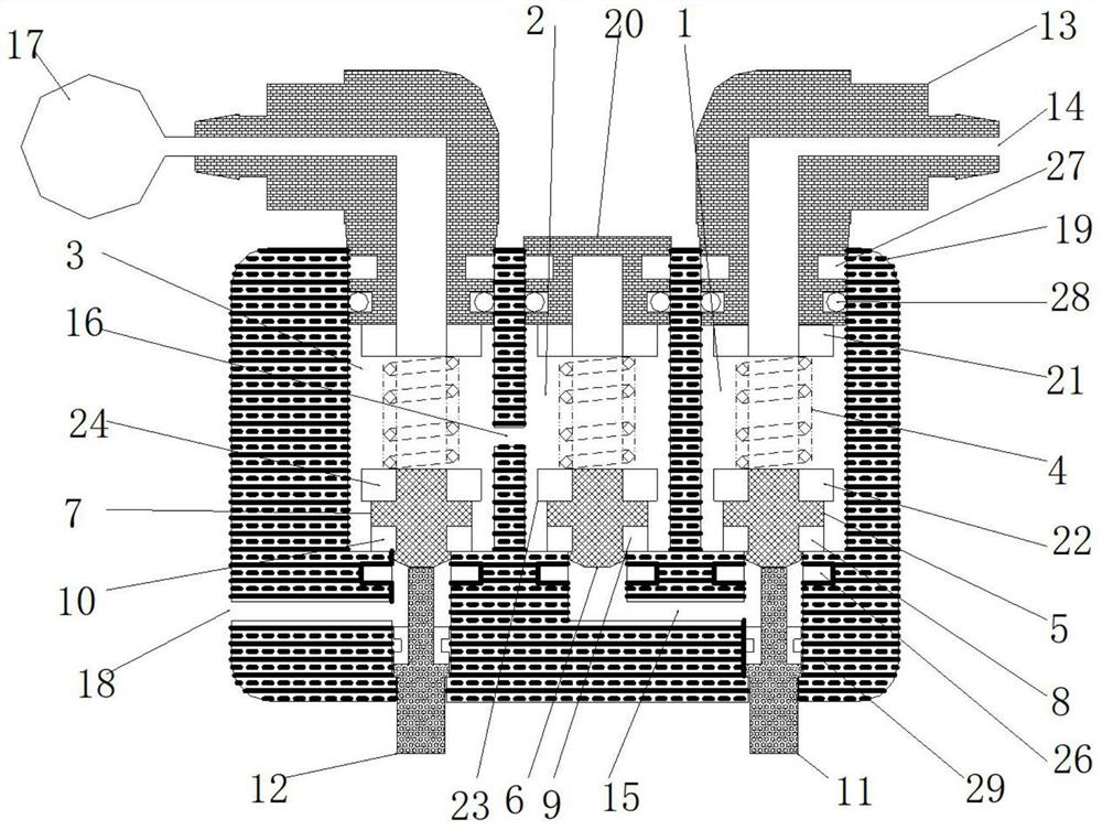
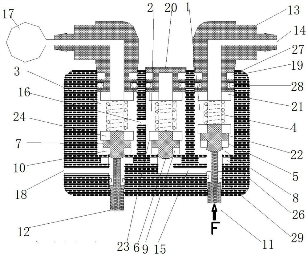
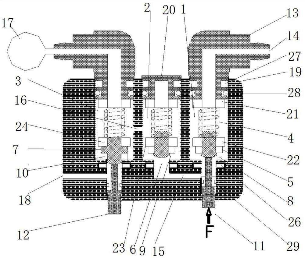
[0034] Magnetic control valves such as figure 1, including a valve body 19, the valve body 19 is sequentially provided with an intake valve cavity 1, a check valve cavity 2 and an exhaust valve cavity 3 from one side to the other; the intake valve cavity 1, the The check valve cavity 2 and the exhaust valve cavity 3 are respectively provided with a valve core spring 4 and an intake valve core framework 5, a check valve core framework 6 and an exhaust valve core framework located below the valve core spring 4. 7. The bottoms of the intake valve core skeleton 5 and the exhaust valve core skeleton 7 are in contact with the upper ends of the intake push rod 11 and the exhaust push rod 12 respectively; the top of the intake valve cavity 1 is in contact with the intake connector 13 The connector air inlet 14 is communicated and connected; the top of the exhaust valve cavity 3 is communicated and connected with the gas port of the exhaust connector, and the gas port of the exhaust co...
Embodiment 2
[0040] The magnetic control valve described in embodiment 1 can also be preferably, such as Figure 10 , An intake connection snap ring 27 is installed between the intake connector 13 and the valve body 19 .
[0041] An exhaust connection snap ring is connected between the exhaust connector and the valve body 19 .
[0042] Also preferably, an air inlet connector sealing ring 28 is installed between the air inlet connector 13 and the valve body 19 .
[0043] Also preferably, an exhaust connector sealing ring is installed between the exhaust connector and the valve body 19 .
[0044] It may also be preferred that an intake push rod sealing ring 29 is installed between the intake push rod 11 and the inner wall of the intake valve cavity 1 .
[0045] Also preferably, an exhaust push rod sealing ring is installed between the exhaust push rod 12 and the inner wall of the exhaust valve cavity 3 .
[0046] It can also be preferred that the intake connector 13, the exhaust connector...
PUM
 Abstract
Description
Claims
Application Information
 - R&D
- Intellectual Property
- Life Sciences
- Materials
- Tech Scout
- Unparalleled Data Quality
- Higher Quality Content
- 60% Fewer Hallucinations
Browse by: Latest US Patents, China's latest patents, Technical Efficacy Thesaurus, Application Domain, Technology Topic, Popular Technical Reports.
© 2025 PatSnap. All rights reserved.Legal|Privacy policy|Modern Slavery Act Transparency Statement|Sitemap|About US| Contact US: help@patsnap.com


