Magnetic control valve

A technology of magnetic control and valve body, which is applied in the direction of control valves, lifting valves, valve devices, etc., can solve the problems of increased hardness of control valve gaskets, reduced sealing pressure of valve cores, and reduced sealing effects, etc., to improve low temperature resistance , prevent air pressure leakage, improve the effect of service life

Active Publication Date: 2022-07-15
TIANJIN SHANCHUANTE PRECISION MOLD
View PDF0 Cites 0 Cited by
  • Summary
  • Abstract
  • Description
  • Claims
  • Application Information

AI Technical Summary

Problems solved by technology

[0003] The present invention provides a magnetic control valve, which aims to solve the problem that the seal of the control valve in the prior art is completely dependent on the pressure of the valve core spring, resulting in frequent compression of the valve core spring, the spring compression force is weakened, and the sealing pressure of the valve core is reduced. decrease, resulting in pressure gas leakage; in addition, when the ambient temperature decreases (such as below -20°C), the hardness of the control valve gasket increases at low temperature, further reducing the sealing effect, resulting in the problem of pressure gas leakage

Method used


Image

  • Magnetic control valve
  • Magnetic control valve
  • Magnetic control valve

Examples


Embodiment 1

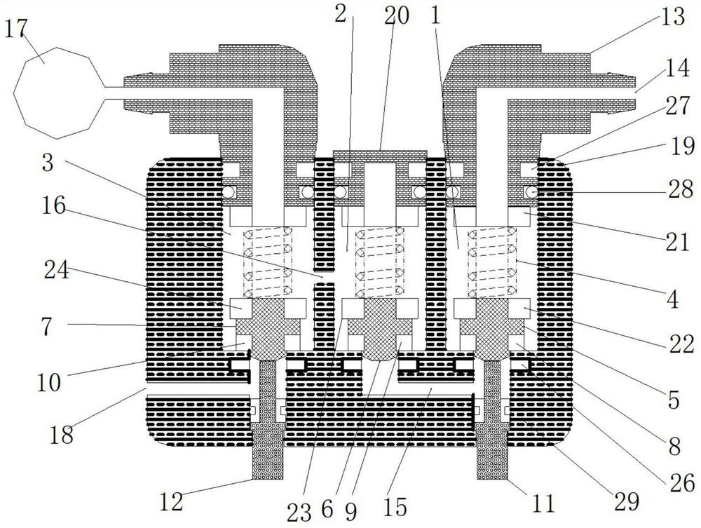
[0034] Magnetic control valves such as figure 1, including the valve body 19, the valve body 19 is sequentially provided with an intake valve chamber 1, a check valve chamber 2 and an exhaust valve chamber 3 from one side to the other; the intake valve chamber 1, the The check valve cavity 2 and the exhaust valve cavity 3 are respectively provided with a valve core spring 4 and an intake valve core frame 5, a check valve core frame 6 and an exhaust valve core frame located under the valve core spring 4. 7; the bottoms of the intake valve core frame 5 and the exhaust valve core frame 7 are in contact with the upper ends of the intake push rod 11 and the exhaust push rod 12 respectively; The connector air inlet 14 is connected in communication; the top of the exhaust valve cavity 3 is in communication with the air port of the exhaust connector, and the air port of the exhaust connector is in communication with the air port of the pressure airbag 17; the check valve The upper en...

Embodiment 2

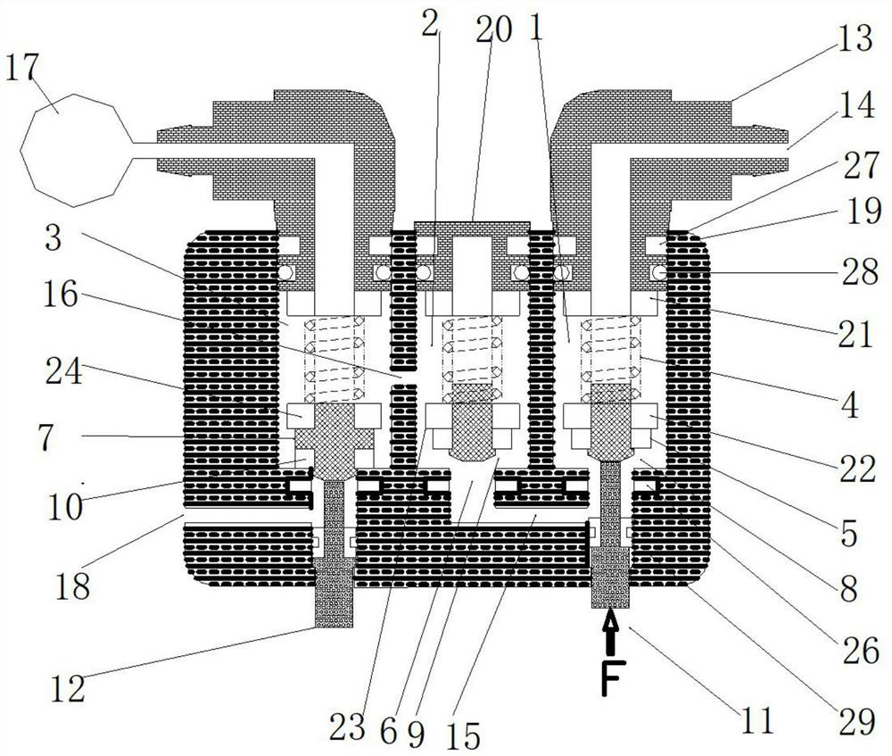
[0040] The magnetic control valve described in Embodiment 1 can also be preferred, such as Figure 10 , an intake connection snap ring 27 is installed between the intake connector 13 and the valve body 19 .

[0041] An exhaust connection snap ring is connected between the exhaust connector and the valve body 19 .

[0042] It may also be preferred that an intake connector sealing ring 28 is installed between the intake connector 13 and the valve body 19 .

[0043] It may also be preferred that an exhaust connector sealing ring is installed between the exhaust connector and the valve body 19 .

[0044] It is also preferred that an intake push rod sealing ring 29 is installed between the intake push rod 11 and the inner wall of the intake valve cavity 1 .

[0045] It is also preferable that an exhaust push rod sealing ring is installed between the exhaust push rod 12 and the inner wall of the exhaust valve cavity 3 .

[0046] Also preferably, the intake connector 13, the exhau...


PUM


Abstract

In the magnetic control valve disclosed in the present invention, the intake valve core frame, the check valve core frame, and the exhaust valve core frame are respectively connected with the intake valve core magnetic ring, the check valve core magnetic ring and the exhaust valve core magnetic ring. The valve core magnetic ring, the intake valve magnetic gasket, the check valve magnetic gasket and the exhaust valve magnetic gasket form a valve core group with an integrated structure; It avoids the failure of spring elastic force, maintains the sealing effect, and improves the service life of the product; it uses a magnetic magnetic gasket to increase the sealing pressure, prevent air pressure leakage, and at the same time improve the low temperature resistance, and still has excellent sealing performance at extremely low temperatures.

Description

technical field [0001] The invention belongs to the technical field of valve bodies, in particular to a magnetic control valve. Background technique [0002] The sealing of the control valve in the prior art is mostly completely dependent on the pressure of the valve core spring. With the frequent compression of the valve core spring, the failure of the spring compression force is weakened, so that the valve core sealing pressure is reduced, thereby causing the pressure gas to leak; in addition, the ambient temperature When the temperature is lowered (for example, below -20 °C), the hardness of the control valve gasket increases at low temperature, which further reduces the sealing effect, resulting in the leakage of pressure gas. SUMMARY OF THE INVENTION [0003] The invention provides a magnetic control valve, which aims to solve the problem that the sealing of the control valve in the prior art is completely dependent on the pressure of the valve core spring, resulting ...

Claims


Application Information

Patent Timeline
Patent Type & Authority Patents(China)
IPC IPC(8): F16K1/00F16K1/32F16K1/36F16K1/46F16K15/06F16K15/18F16K31/06F16K31/08
CPCF16K1/00F16K1/32F16K1/36F16K1/46F16K15/063F16K15/18F16K31/0655F16K31/08
Inventor 金银石
Owner TIANJIN SHANCHUANTE PRECISION MOLD
Why Eureka
Try Eureka