
Electronic equipment

A technology of electronic equipment and electronic devices, which is applied in the field of electronic equipment and can solve problems such as clutter generated during ultrasonic reflection and interference with measurement results

Active Publication Date: 2021-04-30
VIVO MOBILE COMM CO LTD
View PDF4 Cites 0 Cited by
  • Summary
  • Abstract
  • Description
  • Claims
  • Application Information

AI Technical Summary

Problems solved by technology

[0005] This application discloses an electronic device, which can solve the problem that if the surface of the light-transmitting cover is blocked by other objects when the current electronic device measures the thickness of the light-transmitting cover, clutter will be generated during the ultrasonic reflection process, and the clutter will interfere with the measurement result. question

Method used


Image

  • Electronic equipment
  • Electronic equipment
  • Electronic equipment

Examples


Embodiment Construction

[0024] In order to make the purpose, technical solution and advantages of the present application clearer, the technical solution of the present application will be clearly and completely described below in conjunction with specific embodiments of the present application and corresponding drawings. Apparently, the described embodiments are only some of the embodiments of the present application, rather than all the embodiments. Based on the embodiments in this application, all other embodiments obtained by persons of ordinary skill in the art without making creative efforts belong to the scope of protection of this application.

[0025] The technical solutions disclosed in various embodiments of the present application will be described in detail below with reference to the accompanying drawings.

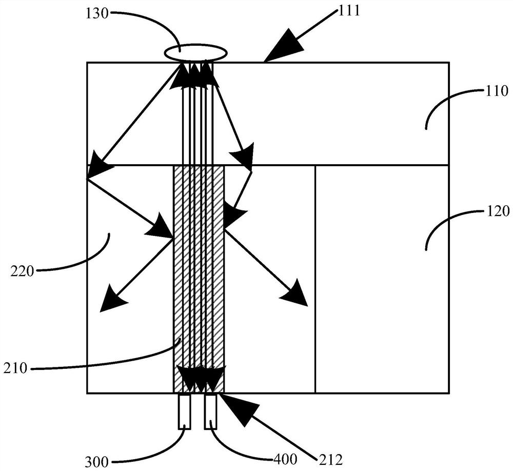
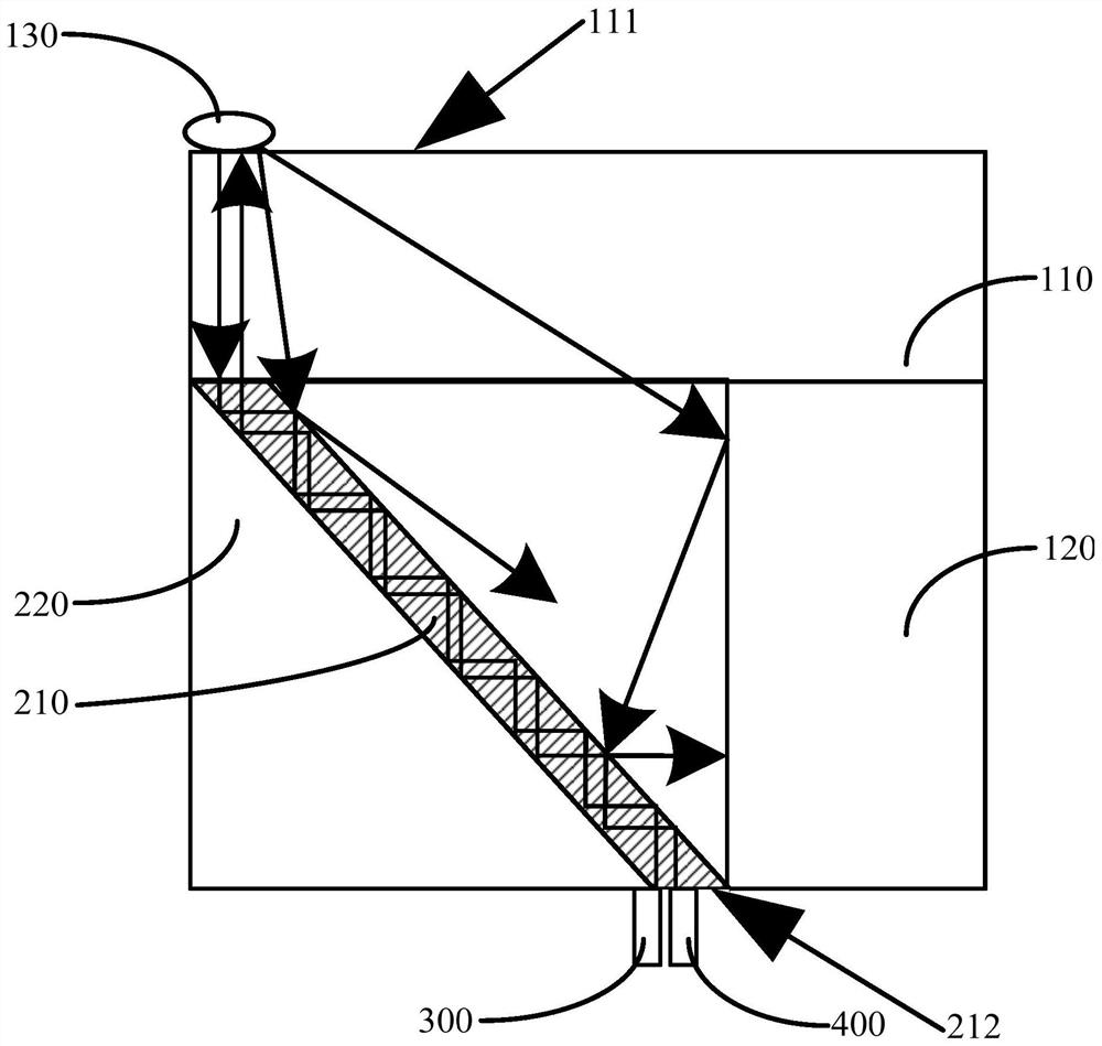
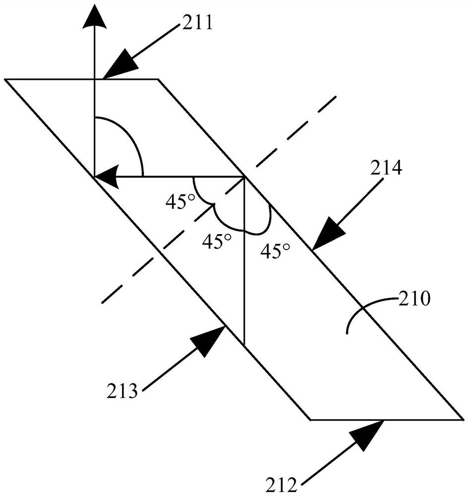
[0026] Such as Figure 1-Figure 3 As shown, the present application provides an electronic device, which includes a first structural member 110 and a thickness detection device.

...


PUM


Abstract

The invention discloses electronic equipment, and belongs to the field of communication equipment. The electronic equipment comprises a first structural part which is provided with a first surface and a second surface which are opposite and are arranged in parallel, and a thickness detection device facing the second surface. A propagation part of the thickness detection device is provided with a third surface and a fourth surface which are opposite and arranged in parallel, the third surface is attached to the second surface, the propagation part comprises a conduction sub-part and an isolation sub-part arranged around the conduction sub-part, and the ultrasonic absorption coefficient of the isolation sub-part is larger than the ultrasonic absorption coefficient of the conduction sub-part. A first end face of the conduction sub-part is located on the third surface, a second end face is located on the fourth surface, and an ultrasonic transmitting part and an ultrasonic receiving part of the thickness detection device are attached to the second end face. The electronic equipment can solve the problem that when the thickness of a light-transmitting cover plate is measured by the existing electronic equipment, if the surface of the light-transmitting cover plate is shielded by other objects, clutters can be generated in the ultrasonic reflection process, and the clutters can interfere with the measurement result.

Description

technical field [0001] The present application belongs to the technical field of communication equipment, and in particular relates to an electronic equipment. Background technique [0002] With the advancement of science and technology, electronic devices such as mobile phones play an important role in people's production and life. Electronic devices are generally equipped with display modules. Display modules usually include a display screen and a transparent cover that are attached to each other. The thickness of the board will affect the photosensitivity of the display module and the infrared noise floor. Therefore, the thickness of the light-transmitting cover is usually known during the use of the electronic device. [0003] At present, the thickness of the light-transmitting cover plate is usually measured by direct measurement. By injecting ultrasonic waves from one side of the display module along the thickness direction of the display module, the ultrasonic waves a...

Claims


Application Information

Patent Timeline
Patent Type & Authority Applications(China)
IPC IPC(8): G01B17/02
CPCG01B17/02
Inventor 艾海强
Owner VIVO MOBILE COMM CO LTD
Learn More