Connector equipment for stabilizing terminal

A connector and terminal technology, which is applied in the field of connector equipment with stable terminals, can solve the problems of difficult to remove, sticking to threaded rods, etc.

Inactive Publication Date: 2021-04-30
刘培元
View PDF0 Cites 2 Cited by
  • Summary
  • Abstract
  • Description
  • Claims
  • Application Information

AI Technical Summary

Problems solved by technology

[0003] Since the solid terminal connector fixes the wire by screwing in the nut terminal, if the wire uses a multi-strand thin copper wire inner core, it is easy for the nut terminal to twist the thin copper wire on the wire inner core when screwing in. Single tearing, so that the disconnected thin copper wire has to bear the energy of the circuit current alone, so the disconnected single thin copper wire will be melted by high temperature and stick to the outer surface of the threaded rod of the nut terminal, which is difficult to remove

Method used


Image

  • Connector equipment for stabilizing terminal
  • Connector equipment for stabilizing terminal
  • Connector equipment for stabilizing terminal

Examples


Embodiment 1

[0026] For example figure 1 -example Figure 5 Shown:

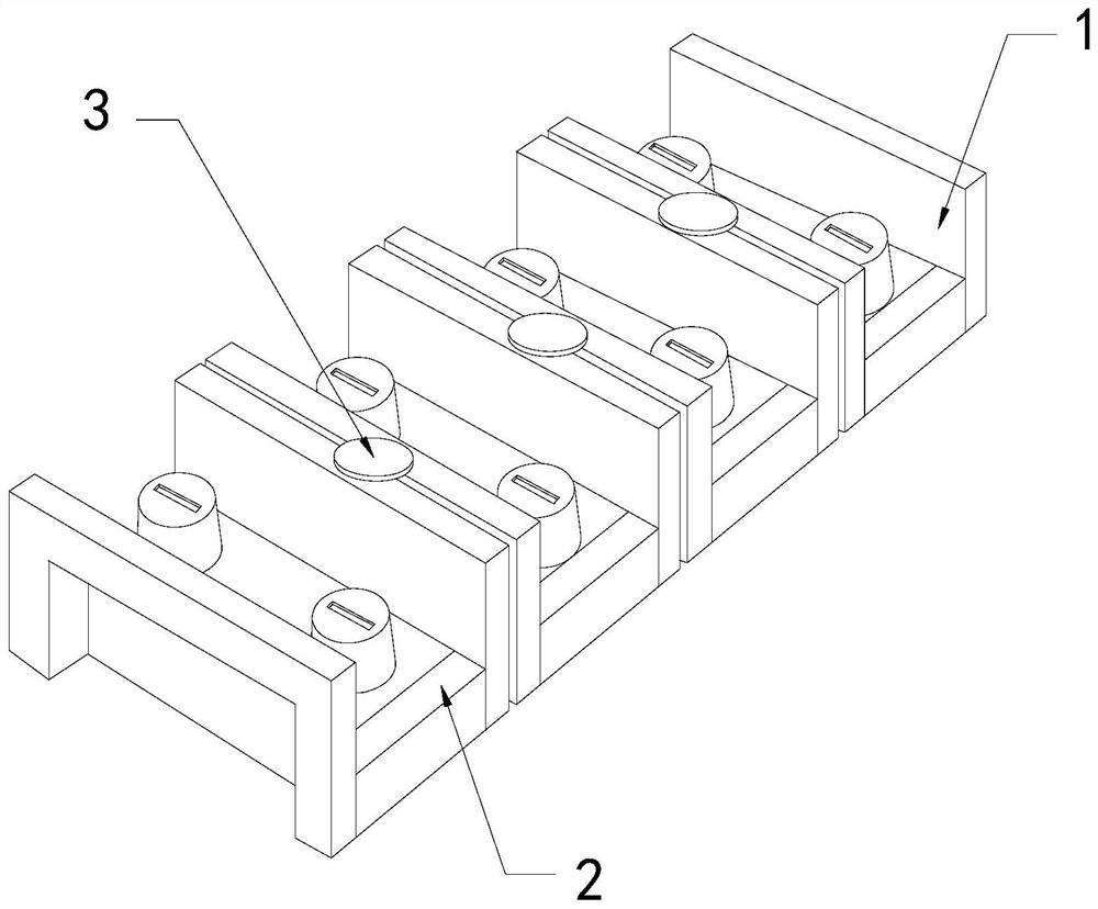
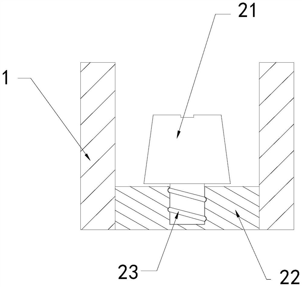
[0027] The present invention provides a connector device for stabilizing terminals, the structure of which includes a partition 1, a connecting mechanism 2, and an engaging piece 3, the connecting piece 3 is installed between the upper ends of two partitions 1, and the connecting mechanism 2 and The partition 1 is an integrated structure; the connecting mechanism 2 includes a nut terminal 21, a lower connecting plate 22, and a threaded convex surface 23, the nut terminal 21 is threadedly connected with the lower connecting plate 22, and the threaded convex surface 23 is connected to the nut Terminal 21 is an integrated structure.

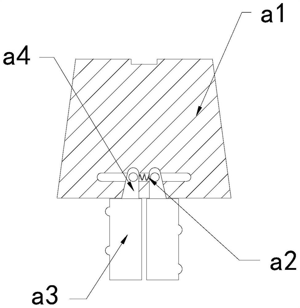
[0028] Wherein, the nut terminal 21 includes a top block a1, a booster bar a2, a threaded rod a3, and a transition block a4, the booster bar a2 is installed between two transition blocks a4, and the threaded rod a3 is embedded in The bottom position of the transition block a4, the transition...

Embodiment 2

[0034] For example Image 6 -example Figure 8 Shown:

[0035] Wherein, the overhanging plate b1 includes a side swing plate b11, a bearing plate b12, a joint plate b13, and an elastic strip b14, the side swing plate b11 is movably engaged with the load plate b12, and the load plate b12 is embedded in the joint plate The right end position of b13, the elastic strip b14 is installed on the inner wall position of the side swing plate b11 and the bearing plate b12, the side swing plate b11 is provided with two, and evenly distributed symmetrically on the load plate b12. The throwing force generated by the extension can make the side swing plate b11 swing outward along the elastic bar b14.

[0036] Wherein, the side swing plate b11 includes a clearing groove c1, a positioning block c2, a plate c3, and a fixing ring c4. The clearing groove c1 is embedded and fixed on the upper surface of the plate c3. As an integrated structure, the fixing ring c4 is connected with the plate c3,...


PUM


Abstract

The invention discloses connector equipment for stabilizing a terminal. The connector equipment structurally comprises two partition plates, a connecting mechanism and a connecting piece, the connecting piece is mounted between the upper ends of the two partition plates, the connecting mechanism and the partition plates are of an integrated structure, and when a nut terminal on the connecting mechanism is completely screwed out of a lower connecting plate upwards, through throwing force generated by swinging of an outer contact plate, the outwards-extending plate can extend outwards along the contact plate and can stretch out and draw back repeatedly along the contact plate under the cooperation of the springback piece, and therefore thin copper wires melted and attached to the outer surface of the threaded rod can be pushed away; the situation that a single thin copper wire can be melted by high temperature to be attached to the outer surface of a threaded rod of a nut terminal and is difficult to remove is effectively avoided, and the side swing plates can be swung and unfolded towards the two sides along the bearing plate through throwing force generated by outward extending of the outward extending plate; therefore, the removing groove can scrape off the thin copper wires attached to the outer surface of the outwards-extending plate when the side swing plate swings outwards.

Description

technical field [0001] The invention relates to the field of terminals and connectors, in particular to a connector device for stabilizing terminals. Background technique [0002] The solid terminal connector is a device used to realize the connection of electrical circuits. By winding the electrical wires on the nut terminal on the solid terminal connector, screwing the nut terminal into the solid terminal connector, and then connecting the electrical wire at the other end If the wires are fixed in the same way, the electrical circuit connection at both ends can be realized. Based on the above description, the inventors found that the existing connector device with stable terminals mainly has the following deficiencies, for example: [0003] Since the solid terminal connector fixes the wire by screwing in the nut terminal, if the wire uses a multi-strand thin copper wire inner core, it is easy for the nut terminal to screw the thin copper wire on the inner core of the wire....

Claims


Application Information

Patent Timeline
IPC IPC(8): H01R4/34H01R9/24
CPCH01R4/34H01R9/24
Inventor 许惠龙
Owner 刘培元
Why Eureka
Try Eureka