Motor and engine using same
An electromagnetic and brush technology, applied in the direction of electric components, electrical components, electromechanical devices, etc., can solve the problems of commutator brush wear, affecting the reliability of the motor and its system, and achieve reliable work, good motor performance, and economical effect of space
- Summary
- Abstract
- Description
- Claims
- Application Information
AI Technical Summary
Problems solved by technology
Method used
Image

Examples
Embodiment 1
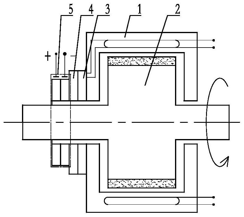
[0043] a motor such as figure 1 As shown, it includes an electromagnetic counterpart A1, an electromagnetic counterpart B2, a commutator 3, a commutator brush 4 and an electric ring 5, and the electromagnetic counterpart A1 and the electromagnetic counterpart B2 are arranged corresponding to each other, so The electromagnetic corresponding body B2 is rotatably arranged, the commutator 3 is arranged on the electromagnetic corresponding body A1 and is arranged in electrical communication with the winding arranged on the electromagnetic corresponding body A1, and the commutator brush 4 is set corresponding to the commutator 3, the electric ring 5 is electrically connected to the commutator brush 4, and the commutator brush 4 and the electric ring 5 are set on the electromagnetic counterpart On B2, a power generation and power supply interface is provided on the winding of the electromagnetic counterpart A1.
[0044] As an alternative embodiment, the magnetic field on the electro...
Embodiment 2
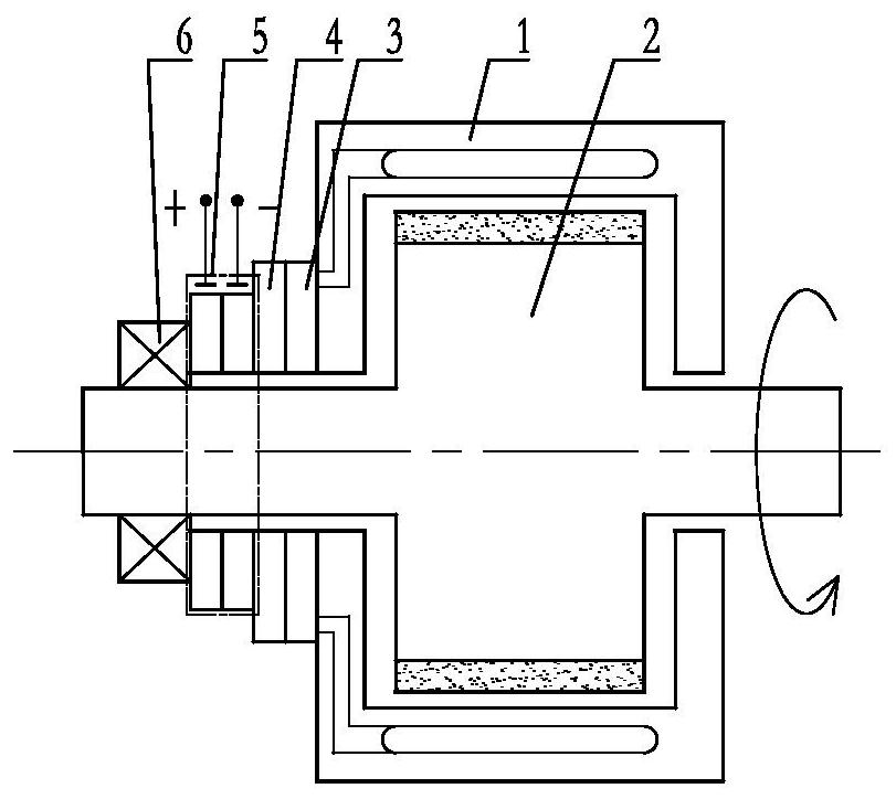
[0050] a motor such as figure 2 As shown, it includes an electromagnetic counterpart A1, an electromagnetic counterpart B2, a commutator 3, a commutator brush 4, an electric ring 5 and a clutch 6, and the electromagnetic counterpart A1 and the electromagnetic counterpart B2 correspond to each other The electromagnetic corresponding body B 2 is rotatably arranged, the commutator 3 is arranged on the electromagnetic corresponding body A1 and is arranged in electrical communication with the windings arranged on the electromagnetic corresponding body A1, and the commutator The brush 4 is arranged corresponding to the commutator 3, the electric ring 5 is electrically connected to the commutator brush 4, and the commutator brush 4 and the electric ring 5 are rotatably arranged, so The clutch switching between the commutator brush 4 and the commutator 3 is controlled and set by the clutch 6 .
[0051] As an alternative embodiment, the magnetic field on the electromagnetic counterpa...
Embodiment 3
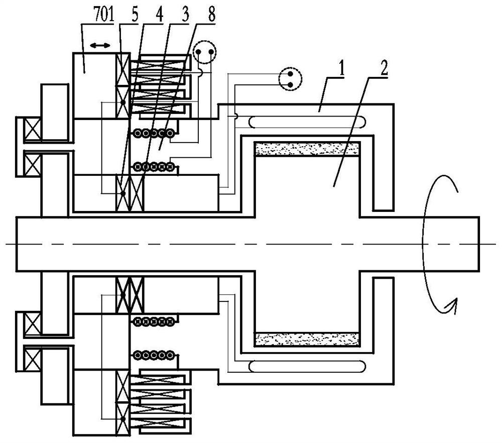
[0058] a motor such as figure 2 As shown, it includes an electromagnetic counterpart A1, an electromagnetic counterpart B2, a commutator 3, a commutator brush 4, an electric ring 5 and a clutch 6, and the electromagnetic counterpart A1 and the electromagnetic counterpart B2 correspond to each other The electromagnetic corresponding body B 2 is rotatably arranged, the commutator 3 is arranged on the electromagnetic corresponding body A1 and is arranged in electrical communication with the windings arranged on the electromagnetic corresponding body A1, and the commutator The brush 4 is arranged corresponding to the commutator 3, the electric ring 5 is electrically connected to the commutator brush 4, and the commutator brush 4 and the electric ring 5 are rotatably arranged, so The clutch switch between the electromagnetic corresponding body B 2 and the rotating body including the commutator brush 4 and the electric ring 5 is controlled by the clutch 6 .
[0059] As an alternat...
PUM
 Abstract
Description
Claims
Application Information
 - Generate Ideas
- Intellectual Property
- Life Sciences
- Materials
- Tech Scout
- Unparalleled Data Quality
- Higher Quality Content
- 60% Fewer Hallucinations
Browse by: Latest US Patents, China's latest patents, Technical Efficacy Thesaurus, Application Domain, Technology Topic, Popular Technical Reports.
© 2025 PatSnap. All rights reserved.Legal|Privacy policy|Modern Slavery Act Transparency Statement|Sitemap|About US| Contact US: help@patsnap.com