A motor, a motor drive system, an electric push rod, and an electric reducer

A technology of motor drive system and screw rod, which is applied in the field of motor and motor drive system, electric reducer, and electric push rod. It can solve the problems of failure to start, affect the accuracy of the motor, and the movement of the shaft, so as to reduce noise and vibration and achieve excellent performance. Motor performance, the effect of eliminating friction loss

Active Publication Date: 2022-01-14
嵊州市宏诺机电有限公司
View PDF12 Cites 0 Cited by
  • Summary
  • Abstract
  • Description
  • Claims
  • Application Information

AI Technical Summary

Problems solved by technology

During the operation of the worm gear mechanism, the shaft is pushed and pulled in the axial direction, which easily causes the shaft to move in the axial direction; when the shaft is pulled outward, the end surface of the shaft sleeve on the shaft and the internal interference structure of the motor are in close contact with each other. If the motor is tight, there is friction between the surfaces inside the motor, which generates a large friction force. The motor needs to overcome this friction force to perform additional work, resulting in waste of energy consumption, and it is easy to cause wear inside the motor, which affects the accuracy of the motor; and when After the motor stops at this position, when the motor restarts, the motor needs to overcome the greater static friction between the surfaces and the resistance torque of its own startup, which may cause the motor to have too much resistance and fail to start, which will affect the kitchen appliances. normal operation of the equipment

Method used


Image

  • A motor, a motor drive system, an electric push rod, and an electric reducer
  • A motor, a motor drive system, an electric push rod, and an electric reducer
  • A motor, a motor drive system, an electric push rod, and an electric reducer

Examples


Embodiment 1

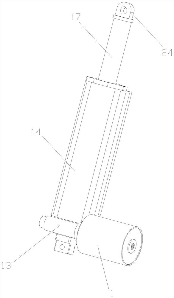
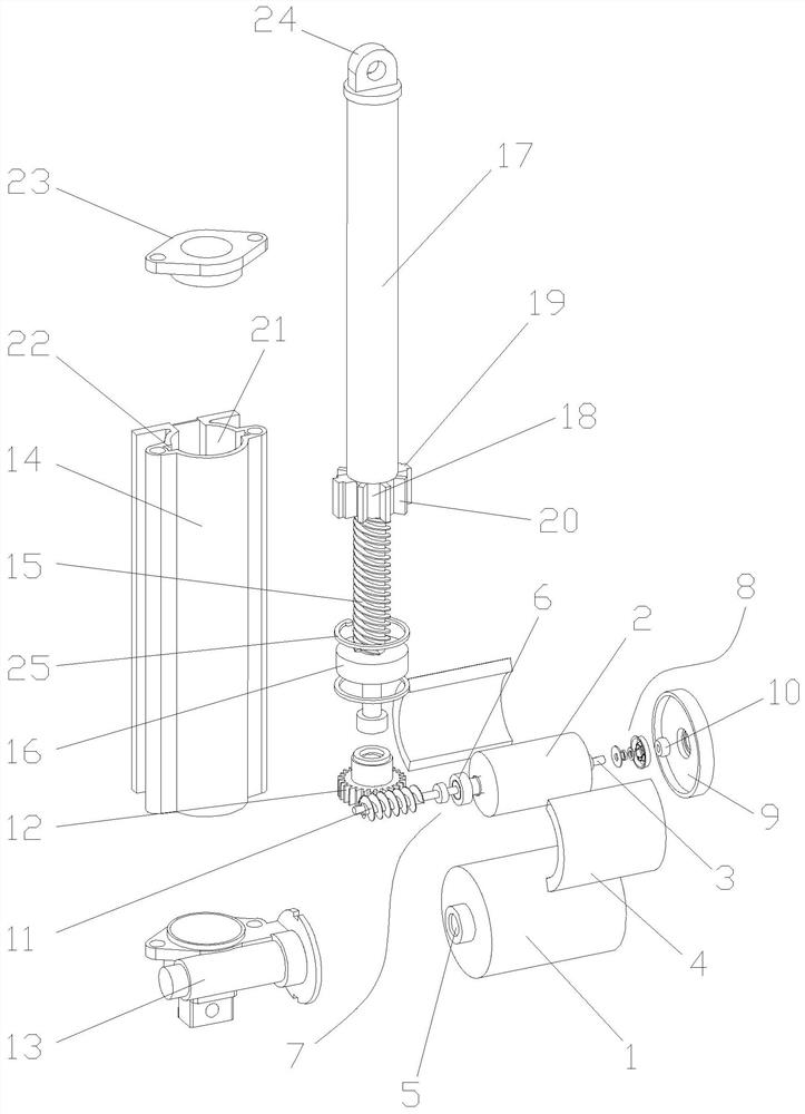
[0030] Embodiment 1: The embodiment of the present invention discloses a motor, such as Figure 1-7 As shown, it is especially suitable for kitchen appliances. The motor drives the worm 11 and drives the worm gear 12 to run, so as to realize the drive of the components in the kitchen appliances.

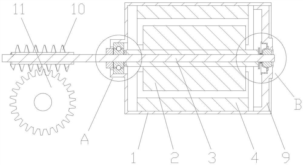
[0031] Specifically, the motor includes a casing 1 having a front end shaft hole 5 and a rear end shaft hole 901, and the inside of the casing 1 has a rotor assembly 2 and a stator assembly 4; the rotor assembly 2 is a rotating shaft 3 surrounding a coil, and the rotating shaft The two ends of 3 are respectively carried by the front end shaft hole 5 and the rear end shaft hole 901 to realize rotation. The stator assembly 4 is a permanent magnet installed on the inner wall of the housing 1. The magnets are used to surround the outer side of the rotor coil and cooperate with each other; in order to increase For the stability of the rotating shaft 3 during operation, a bearing 6 is inst...

Embodiment 2

[0046] Embodiment 2: The embodiment of the present invention also discloses another kind of motor. The specific structure of the motor is basically the same as that of the above-mentioned embodiment. Different, specifically, in the present embodiment, the shaft sleeve 10 is set to a semi-closed structure, and the outer anti-snag part 702 can be canceled according to the use situation, and the end of the inner hole of the shaft sleeve 10 has a contact surface 101, which can be connected with The axial load of the rotating shaft 3 is supported, and the pressing position between the rotating shaft 3 and the contact surface 101 is located on the axis, which can reduce the friction between the rotating shaft 3 and the contact surface 101 during the rotation process, and reduce the noise and wear of the motor; The anti-channeling part 702 can play a double supporting effect, and the gap between the contact surface 101 and the end surface of the rotating shaft 3 is slightly smaller th...

Embodiment 3

[0049] Embodiment Three: The embodiment of the present invention discloses a motor drive system, such as image 3 As mentioned above, the motor drive system has the motor in the above-mentioned embodiments.

[0050] The motor drive system also includes a worm gear assembly. The worm gear assembly is composed of a worm gear 12 and a worm 11 that are meshed with each other. The worm 11 is installed on the rotating shaft 3. The worm gear 12 can also rotate stably through the shaft support. The rotation of the driven worm 11 through the motor , and then transmitted to the rotation of the worm gear 12 to realize the output of power; on the one hand, the worm gear and worm assembly can realize the deceleration of the rotation and convert it into a larger output torque; force to support, reduce the axial movement of the worm 11 and the rotating shaft 3, reduce the resulting wear and noise, and increase the stability of the entire motor drive system.


PUM


Abstract

The invention discloses a motor, a motor drive system, an electric push rod, and an electric reducer, which relate to the technical field of motor equipment and aim to solve the problems of axial movement, noise, wear and low efficiency caused by the motor-driven worm gear structure. The key points of its technical solution are: comprising: a housing with a front end shaft hole, and a bearing is arranged in the front end shaft hole; a rotor assembly, which includes a rotating shaft and coils arranged around the telescopic rotating shaft, and one end of the rotating shaft is rotatably connected to the The front end shaft hole; the stator assembly, which includes permanent magnets surrounding the rotating shaft assembly; the anti-channeling assembly, which is used to limit the bidirectional axial movement of the rotating shaft. The invention provides a stable, low-noise, high-efficiency motor and a motor drive structure suitable for a worm gear structure.

Description

technical field [0001] The invention relates to the technical field of motor equipment, in particular to a motor, a motor drive system, an electric push rod, and an electric reducer. Background technique [0002] With the rapid development of the kitchen electrical equipment industry, a large number of linear transmission telescopic devices are required to realize the automatic operation of kitchen equipment in various equipment of kitchen appliances. As the key structure of this type of equipment, worm gear motors directly affect the operation of equipment. situation. However, the worm gear motors currently used in the field of kitchen appliances are generally prone to jamming, resulting in the inability of stable and reliable operation of kitchen appliances. This phenomenon is especially common in range hoods, integrated stoves and other applications. Or the lift glass cannot be opened or closed. [0003] The main reason is that during the operation of the worm gear moto...

Claims


Application Information

Patent Timeline
Patent Type & Authority Patents(China)
IPC IPC(8): H02K7/116H02K7/06H02K5/173H02K7/10
CPCH02K7/1166H02K7/06H02K5/1737H02K7/10
Inventor 鲁锦樑任连军
Owner 嵊州市宏诺机电有限公司
Why Eureka
Try Eureka