A magnetic levitation switched reluctance flywheel motor and its control method

A technology of switched reluctance and flywheel motors, applied in the direction of AC motor control, control systems, electrical components, etc., can solve the problem of nonlinear strong coupling between suspension and power generation systems, limit the critical maximum speed, and cannot realize repeated switching between electric and power generation states, etc. question

Inactive Publication Date: 2017-04-19
NANJING INST OF TECH
View PDF8 Cites 0 Cited by
  • Summary
  • Abstract
  • Description
  • Claims
  • Application Information

AI Technical Summary

Problems solved by technology

[0005] The document "Design of Full-cycle Bearingless Magnetic Levitation Switched Reluctance Generator" published in "Proceedings of China Electrical Engineering Society" in 2011 announced a magnetic levitation switched reluctance full-cycle generator, which can compensate for the power density of the traditional periodic time-sharing power generation mode Low limitations, but there are serious nonlinear strong coupling problems between the suspension in the motor and the power generation system
The invention patent with the application number 201110313992.x "a magnetic levitation switched reluctance generator" and the invention patent with the application number 201210541096.3 "a stator hybrid short magnetic circuit magnetic levitation switched reluctance generator" both announced a hybrid stator In the magnetic levitation switched reluctance generator, the stator adopts a wide-narrow pole hybrid structure, which can weaken the coupling between the generator pole and the levitation pole, but the excitation current still has a great influence on the radial levitation.
[0006] The invention patent of application number 200510040266.X "Bearingless switched reluctance starter generator and control method" proposes a bearingless switched reluctance starter generator and control method, which reduces the Mechanical wear reduces the noise of the motor, but the main winding and the auxiliary winding overlap at the same time, there is a complex nonlinear strong coupling effect, and the effective working areas of the two sets of windings are mutually restrained, which limits the flexibility of the control method selection
The invention patent with the application number of 201310637999.6 "a dual-stator magnetic levitation switched reluctance starter / generator" proposes a double-stator magnetic levitation switched reluctance starter / generator, which effectively weakens the coupling effect of the main winding and the levitation force winding , and the two sets of windings work independently, which increases the flexibility of control. The principle of start-up and power generation is announced. After start-up, power generation is controlled according to the power generation requirements, and repeated switching between electric and power generation states cannot be realized.
[0007] A single-winding hybrid outer rotor magnetic levitation switched reluctance motor published in the invention patent with application number 201310652080.4 adopts a hybrid outer rotor structure of a salient pole rotor and a disc rotor, and simultaneously generates radial There is still coupling between the radial levitation force and the electromagnetic torque, so the decoupling effect of the radial force and torque is poor; at the same time, the radially opposite two-pole windings on the stator are differentially excited at the same time, The two are distributed according to the required radial force and torque, and the suspension force control and torque control are mutually restrained; further, the outer rotor part of the disk will increase the axial length of the motor, resulting in an increase in the volume of the motor and limiting the Its critical maximum speed

Method used


Image

  • A magnetic levitation switched reluctance flywheel motor and its control method
  • A magnetic levitation switched reluctance flywheel motor and its control method
  • A magnetic levitation switched reluctance flywheel motor and its control method

Examples


Embodiment Construction

[0056] The present invention will be further described below in conjunction with the accompanying drawings.

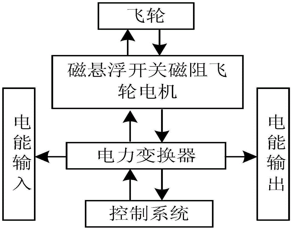
[0057] figure 1 Shown is a schematic diagram of the working principle of the magnetic levitation switched reluctance flywheel motor system of the present invention. When the maglev switched reluctance flywheel motor is driven by the power electronic converter to drive the flywheel to accelerate the rotation, the flywheel stores electrical energy in the form of mechanical energy, and the flywheel system is in the charging mode. At this time, the motor operates as a motor; when there is no need to supply power to the outside, The speed of the flywheel motor is constant, the flywheel energy storage system is in the hold mode, and the motor is on standby at this time; when it is necessary to provide electric energy to the outside, the flywheel rotates at a high speed due to inertia and acts as the prime mover of the system to drag the motor in the system to generate electr...


PUM


Abstract

The invention discloses a magnetic suspension switch magnetic resistance flywheel motor and a control method. The magnetic suspension switch magnetic resistance flywheel motor comprises an inner stator, a rotor and an outer stator. The inner stator (6), the rotor (4) and the outer stator (1) are successively nested in a concentric mode, 12 torque poles (2) are arranged on the inner wall of the outer stator (1) at equal intervals, and the torque poles are wound by main windings (3); eight rotor salient poles (5) are arranged on the outer wall of the rotor (4) at equal intervals; and four suspension poles (7) are arranged on the outer wall of the inner stator (6) at equal intervals, and the suspension poles (7) are wound by suspension force windings (8). According to the invention, the problem of incapability of effectively generating suspension forces when a stator and a rotor are not aligned by use of a conventional magnetic suspension switch magnetic resistance motor is overcome, the radial force and the torque decoupling effect are good, the radial load capability is improved, the suspension force windings are individually controlled simply according to a needed radial suspension force, each main winding on the outer stator is also controlled simply according to needed electromagnetic torque, the control is easy, and a control algorithm is simpler and is more easily realized.

Description

technical field [0001] The invention relates to a magnetic levitation switched reluctance flywheel motor and a control method thereof, which belong to the field of motors. Background technique [0002] As power shortages and environmental problems caused by energy utilization become more and more serious, solar photovoltaic power generation and wind power generation have developed rapidly due to their abundant resources, wide distribution and inexhaustible use. However, the inherent intermittency and randomness of solar photovoltaic power generation and wind power generation will have a significant impact on the safe operation of the power system, so it is particularly urgent to study advanced energy storage technologies, among which flywheel energy storage has long service life, high energy storage density, It has a series of advantages such as no pollution to the environment, easy prevention of overcharge and overdischarge problems, and insensitivity to temperature, and ha...

Claims


Application Information

Patent Timeline
Patent Type & Authority Patents(China)
IPC IPC(8): H02P25/08
Inventor 周云红孙玉坤
Owner NANJING INST OF TECH
Why Eureka
Try Eureka