Bearingless switched reluctance generator

A switched reluctance, generator technology, applied in electrical components, holding devices with magnetic attraction or thrust, etc., can solve problems such as low power density of power generation, improve suspension performance, enhance radial load capacity, and facilitate modeling and control effects

Inactive Publication Date: 2014-04-09
JIANGSU UNIV
View PDF3 Cites 0 Cited by
  • Summary
  • Abstract
  • Description
  • Claims
  • Application Information

AI Technical Summary

Problems solved by technology

[0005] The purpose of the present invention is to propose a magnetically suspended switched reluctance generator with decoupling of the suspension and power generation system and enhanced radial suspension performance. This generator solves the problem of low power density of power generation

Method used


Image

  • Bearingless switched reluctance generator
  • Bearingless switched reluctance generator
  • Bearingless switched reluctance generator

Examples


Embodiment Construction

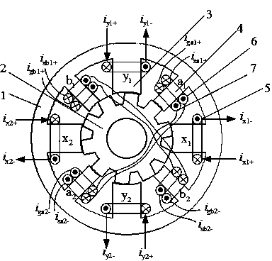
[0028] Such as figure 1 As shown, the structure diagram of the magnetic levitation switched reluctance generator of the present invention adopts a double salient pole structure of 8 / 10 poles, including a stator core 1, a rotor core 2, a levitation pole 3, a generator pole 4, a levitation winding 5, an excitation The winding 6 and the generating winding 7, the floating pole 3 and the generating pole 4 are arranged on the stator core 1 at equal intervals, and the floating pole 3 and the stator pole are wide , generator pole 4 stator pole width , rotor pole width . Independent levitation windings 5 ​​are respectively wound on the four levitation poles 3 , and the required levitation force is obtained by individually controlling the magnitude of the current of each levitation winding 5 . The directional levitation force is determined by the current of the levitation winding 5 and control when When turned on, the resulting Suspension force in the positive direction, ...


PUM


Abstract

The invention discloses a bearingless switched reluctance generator. The generator is of a double-salient structure consisting of a stator iron core and a rotor iron core, wherein four suspension electrodes and four generating electrodes are arranged on the stator iron core at equal interval, and the generating electrodes are opposite pairwise in a radial direction; the width of a stator electrode of each suspension electrode is more than that of a stator electrode of each generating electrode, and the width of a rotor electrode is same as that of the stator electrode of each generating electrode; independent suspension windings are wound on the suspension electrodes respectively; and a drive winding and a generating winding are arranged on the generating electrodes respectively in a lap winding way, and two radial opposite windings are connected in series. According to the bearingless switched reluctance generator, the technical problem of non-linear strong coupling between suspending power and generating voltage is solved, the radial load capability is enhanced, and the suspension performance is improved.

Description

technical field [0001] The invention relates to the field of magnetic levitation switched reluctance motors, in particular to a magnetic levitation switched reluctance generator, which is especially suitable for electric energy compensation in renewable energy power generation systems such as photovoltaics. Background technique [0002] The magnetic suspension bearing winding and the motor stator winding are regularly wound together to realize the bearingless motor. This concept was first proposed by R.Bosch in the late 1980s. Following the magnetic levitation asynchronous motor and the magnetic levitation permanent magnet synchronous motor, the technology of the magnetic levitation switched reluctance motor has also been studied. DC voltage, especially suitable for momentum compensation, peak regulation and load balancing in grid-connected operation of renewable energy sources such as photovoltaics. [0003] The traditional power generation mode of the magnetic levitation ...

Claims


Application Information

Patent Timeline
Patent Type & Authority Patents(China)
IPC IPC(8): H02N15/00
Inventor 周云红孙玉坤黄永红嵇小辅周丽红
Owner JIANGSU UNIV
Why Eureka
Try Eureka