cam mechanism

A cam mechanism and cam technology, applied in the electromechanical field, can solve the problems of dynamic connection, mechanical parts friction damage, and cam mechanism component breakage, etc., and achieve the effects of high reliability, increased electromagnetic control force, and high output accuracy

Active Publication Date: 2018-06-29
NINGBO INST OF MATERIALS TECH & ENG CHINESE ACADEMY OF SCI
View PDF2 Cites 0 Cited by
  • Summary
  • Abstract
  • Description
  • Claims
  • Application Information

AI Technical Summary

Problems solved by technology

However, as far as the actual situation is concerned, according to the statistical analysis of data, the main cause of the failure of the cam mechanism is not the fracture of the parts, but the friction damage of the moving connection and the machine parts. 90% of the work failures are caused by wear and tear.

Method used


Image

  • cam mechanism
  • cam mechanism
  • cam mechanism

Examples


Embodiment Construction

[0049] Preferred embodiments of the present invention will be described in detail below with reference to the accompanying drawings, so as to better understand the purpose, features and advantages of the present invention. It should be understood that the embodiments shown in the drawings are not intended to limit the scope of the present invention, but only to illustrate the essence of the technical solutions of the present invention.

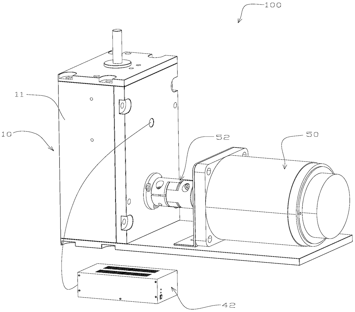
[0050] The invention mainly relates to a non-contact magnetic levitation cam mechanism, which can be widely used in the fields of machine tools, textile machinery, light industry machinery, printing machinery, mechatronics assembly and the like.

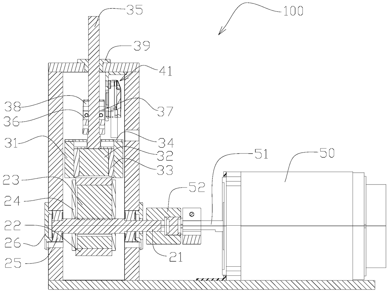
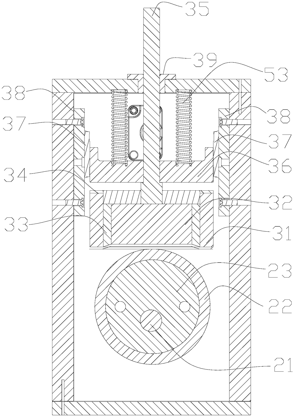
[0051] The cam mechanism of the present invention generally includes a driving part and a driven part. The driving part includes a permanent magnet cam and a main shaft. The driven part includes a permanent magnet and an output shaft. The permanent magnet cam is fixedly connected to the main shaft, an...


PUM


Abstract

The invention discloses a cam mechanism, which includes a seat frame, a driving part and a follower part, the driving part and the follower part are installed on the seat frame, the driving part includes a permanent magnet cam, and the slave The movable part includes a permanent magnet. When the permanent magnet cam rotates, the permanent magnet is reciprocated by the repulsive force of the permanent magnet cam and does not come into contact with the permanent magnet cam. The cam mechanism of the present invention has beneficial effects such as non-contact transmission, high output precision, no friction loss, low vibration, low impact, low noise, no need for lubrication, precise motion transmission capability, and high reliability.

Description

technical field [0001] The invention relates to the electromechanical field, in particular to a cam mechanism. Background technique [0002] In various mechanical equipment, especially in automatic machinery and control devices, various forms of cam mechanisms are widely used, for example, gas distribution cam mechanisms in internal combustion engines, cable cam mechanisms in winding machines, in medicine, Indexing cam mechanisms used in food, packaging and other industries, cam mechanisms in automatic feeders, etc. [0003] The cam mechanism is a high-pair transmission mechanism composed of three main components: the cam, the follower and the frame. The designer only needs to design the cam profile according to the requirements of the working conditions, so that the follower can achieve any given displacement, Speed, acceleration and other motion laws; and because the cam mechanism has the advantages of simple structure, compactness, less failures, and convenient maintenan...

Claims


Application Information

Patent Timeline
Patent Type & Authority Patents(China)
IPC IPC(8): H02K49/10
Inventor 杨桂林赵鹏陈进华张杰陈庆盈张驰
Owner NINGBO INST OF MATERIALS TECH & ENG CHINESE ACADEMY OF SCI
Why Eureka
Try Eureka