
Commutation system and commutation method of high-speed brushless direct current motor

A brush DC motor, high-speed technology, applied in the field of commutation system of high-speed brushless DC motor, can solve the problems of reducing motor performance, increasing system power consumption, affecting commutation accuracy, etc., to save interrupt resources and improve acquisition speed , the effect of increasing the sampling frequency

Active Publication Date: 2021-04-30
NINGBO INST OF TECH BEIHANG UNIV +1
View PDF6 Cites 2 Cited by
  • Summary
  • Abstract
  • Description
  • Claims
  • Application Information

AI Technical Summary

Problems solved by technology

[0002] The brushless DC motor commutation method can use three-way Hall signals or encoders to form six-way commutation signals through the combination of high and low levels. However, the installation of position sensors not only increases the power consumption of the system, but also reduces the reliability of the system. , so the commutation method without position sensor has become a research hotspot in recent years
As a commutation method without a position sensor, the back electromotive force zero-crossing method is widely used in industry because of its simplicity and reliability. commutation method of area integral method
[0003] In the prior art, the commutation of the area integration method generally requires high-frequency sampling of the signal. The sampling circuit is implemented based on software. Since the electrical cycle of the motor is very small when the motor is running at high speed, the sampling density of the integrated signal is low. It will cause the sampling accuracy to drop, cause the calculation of the area to be inaccurate, and lead to commutation errors

Method used


Image

  • Commutation system and commutation method of high-speed brushless direct current motor
  • Commutation system and commutation method of high-speed brushless direct current motor
  • Commutation system and commutation method of high-speed brushless direct current motor

Examples


Embodiment Construction

[0059] In order to understand the above-mentioned purpose, features and advantages of the present invention more clearly, the solutions of the present invention will be further described below. It should be noted that, in the case of no conflict, the embodiments of the present invention and the features in the embodiments can be combined with each other.

[0060] In the following description, many specific details have been set forth in order to fully understand the present invention, but the present invention can also be implemented in other ways different from those described here; obviously, the embodiments in the description are only some embodiments of the present invention, and Not all examples.

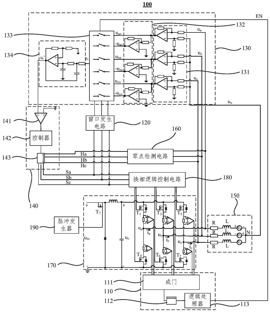
[0061] figure 1 A schematic structural diagram of a commutation system of a high-speed brushless DC motor provided by an embodiment of the present invention, as shown in figure 1 As shown, the commutation system 100 of the high-speed brushless DC motor includes an enable sign...


PUM


Abstract

The embodiment of the invention discloses a commutation system and a commutation method of a high-speed brushless direct current motor. The commutation system comprises an enable signal generation circuit, a window generation circuit, a feedback quantity acquisition circuit and a control circuit. The input end of the feedback quantity acquisition circuit is electrically connected with a three-phase winding and a neutral point of the motor, the enabling end of the feedback quantity acquisition circuit is electrically connected with the output end of the enabling signal generation circuit, and the control end of the feedback quantity acquisition circuit is electrically connected with the output end of the window generation circuit; the feedback quantity acquisition circuit is used for forming a reconstructed suspended back electromotive force according to the enable signal, the window signal, the three-phase terminal voltage and the neutral point voltage, and acquiring a feedback quantity; the feedback input end of the control circuit is electrically connected with the output end of the feedback quantity acquisition circuit, the signal input end of the control circuit is electrically connected with a virtual Hall signal, and the output end of the control circuit is electrically connected with the input end of the window generation circuit; and the control circuit is used for generating a commutation signal according to the feedback quantity and the virtual Hall signal.

Description

technical field [0001] The invention relates to the technical field of motors, in particular to a phase commutation system and a phase commutation method of a high-speed brushless DC motor. Background technique [0002] The brushless DC motor commutation method can use three-way Hall signals or encoders to form six-way commutation signals through the combination of high and low levels. However, the installation of position sensors not only increases the power consumption of the system, but also reduces the reliability of the system. , so the commutation method without position sensor has become a research hotspot in recent years. As a commutation method without a position sensor, the back electromotive force zero-crossing method is widely used in industry because of its simplicity and reliability. A commutation method of the area integral method is proposed. [0003] In the prior art, the commutation of the area integration method generally requires high-frequency sampling...

Claims


Application Information

Patent Timeline
Patent Type & Authority Applications(China)
IPC IPC(8): H02P6/14
CPCH02P6/14Y02P80/10
Inventor 刘刚金浩郑世强陈宝栋张海峰
Owner NINGBO INST OF TECH BEIHANG UNIV
Learn More