
Composite-material casing having an integrated stiffener

A technology of composite materials and reinforced components, which can be used in household appliances, household components, engine components, etc., can solve problems such as complex implementation, and achieve the effects of simplifying reliability, increasing reliability, and reducing weight

Active Publication Date: 2021-04-30
SAFRAN AIRCRAFT ENGINES SAS
View PDF10 Cites 0 Cited by
  • Summary
  • Abstract
  • Description
  • Claims
  • Application Information

AI Technical Summary

Problems solved by technology

However, this solution is complex to implement, especially for the attachment of reinforcements which must be as reliable as possible

Method used


Image

  • Composite-material casing having an integrated stiffener
  • Composite-material casing having an integrated stiffener
  • Composite-material casing having an integrated stiffener

Examples


Embodiment Construction

[0039] The invention is generally applicable to any organic matrix composite casing of a gas turbine.

[0040] The invention will be described below in the context of its application to a fan casing of an aviation gas turbine engine.

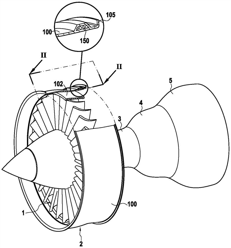
[0041] as by figure 1 Shown very schematically, such an engine comprises a fan 1 , a compressor 2 , a combustion chamber 3 , a high-pressure turbine 4 and a low-pressure turbine 5 arranged at the intake of the engine from upstream to downstream in the flow direction of the gas flow .

[0042] The engine is housed inside a casing comprising several parts corresponding to the different elements of the engine. Thus, the fan 1 is surrounded by the fan case 100 having a solid shape of rotation.

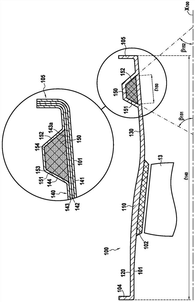
[0043] figure 2The outline of a fan housing 100 made of composite material as can be obtained by the method according to the invention is shown. The inner surface 101 of the housing defines the air intake path. It may be equipped with a wear-resistant...


PUM


Abstract

The invention relates to a method for manufacturing a composite-material casing (100) for a gas turbine, comprising: - using three-dimensional weaving to create a fibrous texture (140) in the form of a strip, - winding the fibrous texture (140) in several superimposed layers (141, 142, 143, 144) onto a mandrel (200) having a profile corresponding to that of the casing to be manufactured, so as to obtain a fibrous preform (300) of a shape corresponding to that of the casing to be manufactured, - densifying the fibrous preform (300) using a matrix. When the last layer of the fibrous texture (140) is wound on the mandrel (200), a stiffening element (150) is interposed between the penultimate layer (143) and the last layer (144) of the fibrous texture. The stiffening element protrudes on the outer surface of the penultimate layer (143) of the fibrous texture (140). The stiffening element (150) has an omega-like shape in axial cross-section.

Description

Background technique [0001] The present invention relates to gas turbine casings, and more particularly, but not exclusively, to gas turbine fan casings for aircraft engines. [0002] The manufacture of a composite shell begins with the production of a fiber texture in the form of a strip, made by three-dimensional weaving between layers of warp threads and layers of weft threads. The fiber texture thus obtained is wound several turns on a mold or tool having the shape of the shell to be produced and this fiber texture is kept between the mold and the section forming the counter-mold to obtain Fiber preforms. [0003] Once the fiber preform is produced, i.e. after winding the fiber texture, the tool carrying the fiber preform is surrounded by a counter-mold and then conveyed to an oven or furnace where the densification of the preform by means of the matrix is ​​performed In particular, the matrix can be obtained by impregnating and curing a resin in a fiber preform. In doc...

Claims


Application Information

Patent Timeline
Patent Type & Authority Applications(China)
IPC IPC(8): B29C70/24F01D25/24
CPCF01D25/24B29C70/24F05D2220/36F05D2300/6012F05D2300/603F05D2250/283F05D2250/75B29C70/32B29C70/865B29L2031/7504B29C70/222Y02T50/60B29B11/16F05D2230/21F05D2240/14F05D2300/6034F01D25/28F01D25/26F01D5/14F05D2300/6031F01D5/141F01D5/282
Inventor 克莱门特·布洛洛谢尔盖·多明格斯文森特·帕斯卡·菲奥雷弗洛伦特·路易斯·安德烈·罗宁安瓦尔·西拉吉
Owner SAFRAN AIRCRAFT ENGINES SAS
Learn More