Programmable fuel dispensing system

Inactive Publication Date: 2005-11-03
WAUGH ERIC S +1
View PDF4 Cites 9 Cited by
  • Summary
  • Abstract
  • Description
  • Claims
  • Application Information

AI Technical Summary

Benefits of technology

[0015] Still another object of the present invention is to provide a more reliable fuel dispensing system by replacing relays, conta

Problems solved by technology

Presently fuel dispensing systems at gas stations and other locales require a complex installation of circuits, relays, and contactors to control fuel dispens

Method used


Image

  • Programmable fuel dispensing system
  • Programmable fuel dispensing system

Examples


Embodiment Construction

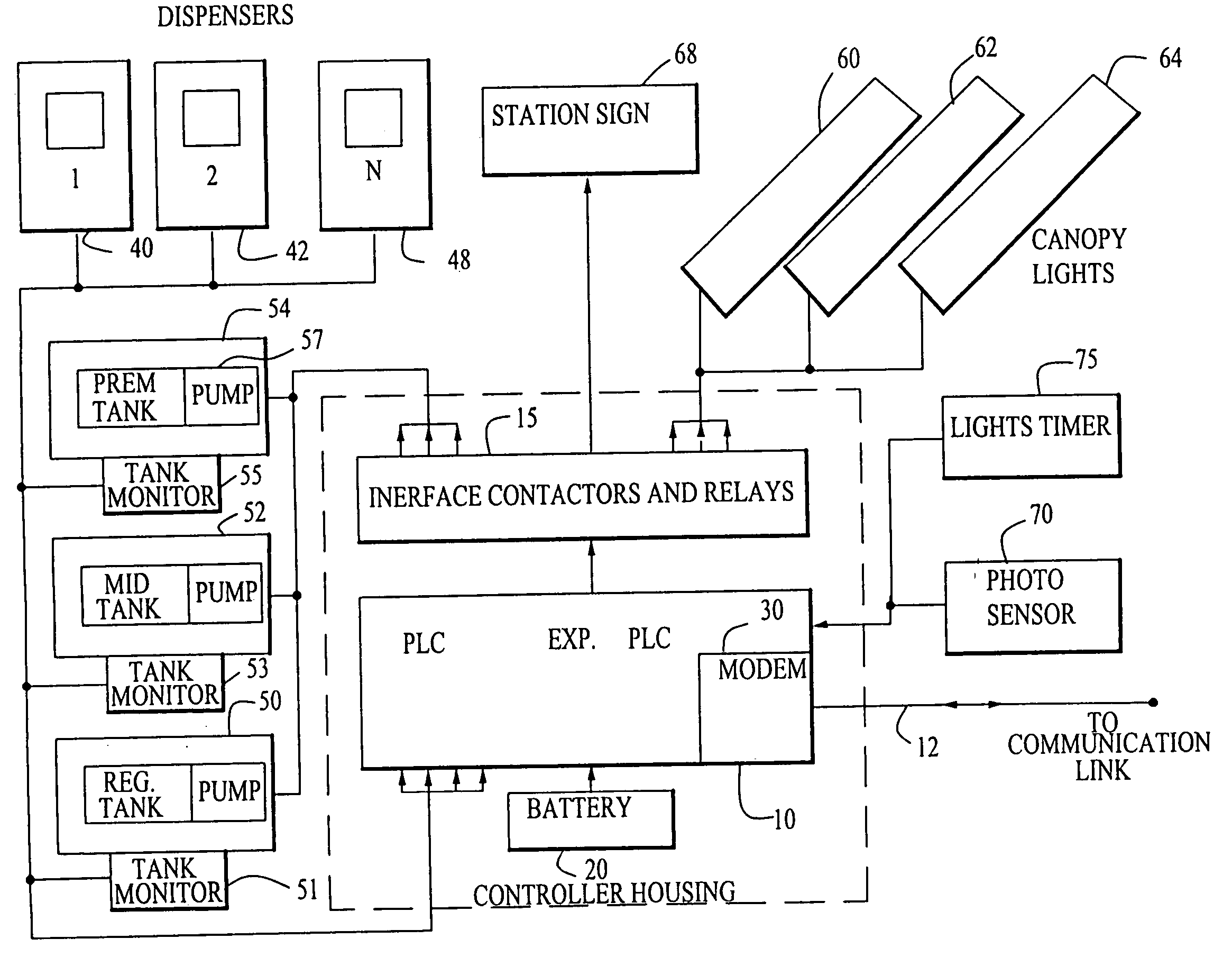
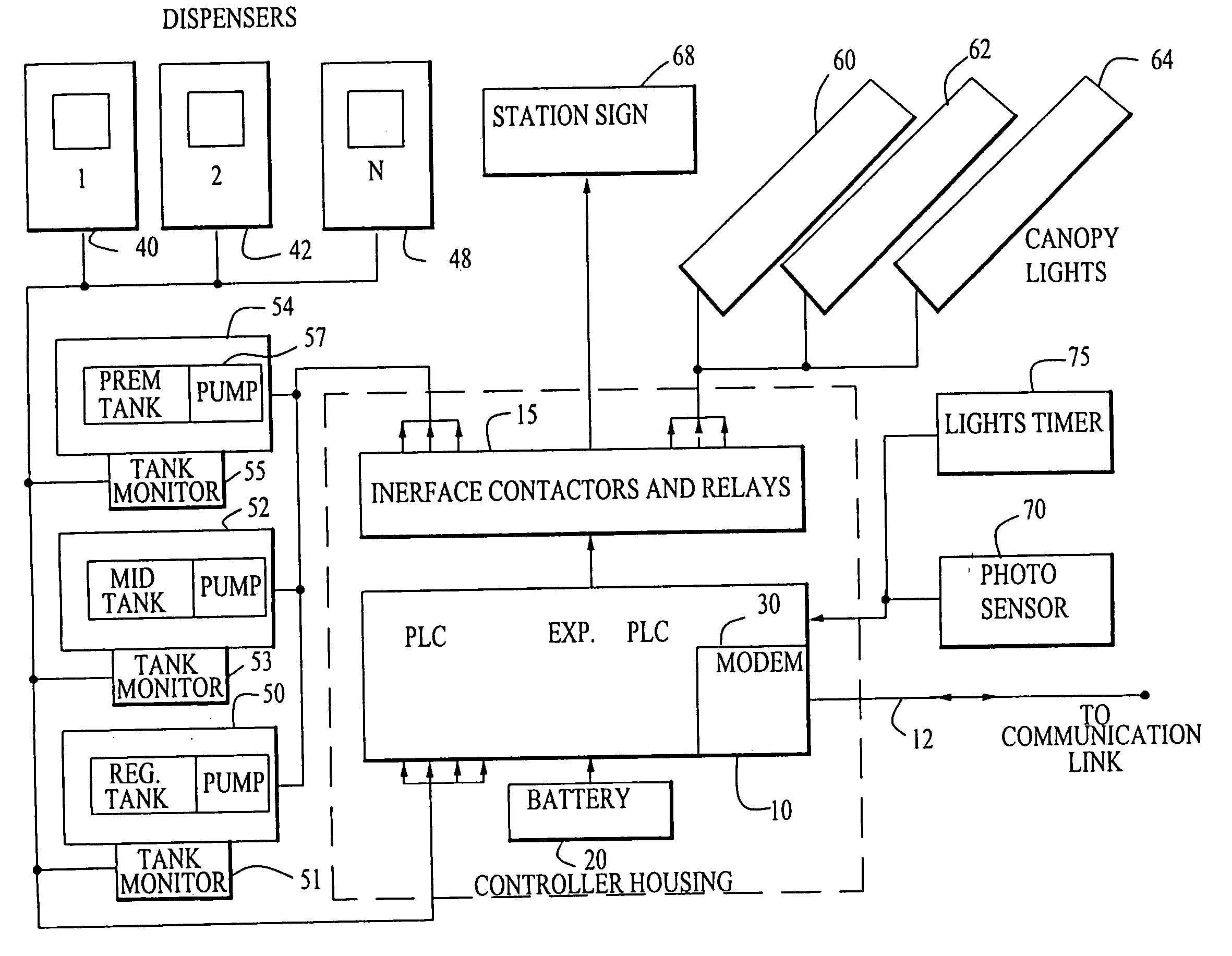
[0027] A schematic block diagram of the programmable solid state fuel dispensing control system according to the invention is illustrated. The system includes a fuel station electronically enhanced control panels. It is an advancement over the electro-mechanical style of equipment typically implemented in conventional present day fuel dispensing systems. The new re-designed system eliminates the all “hard contact” style of numerous relays used to interface with the fueling system, lighting control system, and cash registers.

[0028] Referring to the schematic block diagram of FIG. 1, a novel system is shown in which substantially all hard contacts have been replaced by incorporating a state of the art programmable logic controller (PLC) 10. This solid state device is programmed to receive various inputs and provide outputs that energize the appropriate contactor to turn on dispensers 40, 42, 48, lighting 60, 62, 64, 68, etc. at the appropriate time. An internal clock in the PLC is in...


PUM


Abstract

A centralized fuel or fuel monitoring, control and dispensing system operating under the control of a modern solid state programmable logic controller (PLC) that provides control options with capabilities far exceeding those available from relay logic systems. The system also incorporates compliance with the latest EPA mandates by accepting inputs from water and gasoline sensors that monitor the condition of the required “tank within a tank” dual storage tanks. If a fault condition is detected, the system will force a safety shutdown in the affected part of the installation. The PLC provides centralized monitoring, controlling and reporting functions to the operators of fuel dispensing operations such as self-service gas station complexes and fuel depots. Remote monitoring and programming of the PLC is provided by an internal modem through any available communications link.

Description

BACKGROUND OF THE INVENTION [0001] 1. Field of the Invention [0002] This invention relates to fuel dispensing systems and more particularly relates to a programmable fuel dispensing system. [0003] 2. Background Information [0004] Presently fuel dispensing systems at gas stations and other locales require a complex installation of circuits, relays, and contactors to control fuel dispensing plants. These electronic components are typically mounted in a separate control room on a wall. The relays, contactors, and circuits are to this day usually installed and mounted by an electrician often, in fact usually, without the benefit of an overall wiring diagram. [0005] The sheer number of input and control relays result in a complex installation. Also while these contactors and relays are much more reliable than in the past, so many are required that servicing and repairs are required more frequently than is desirable. Further the lack of a reliable wiring diagram exacerbate the problems. S...

Claims


Application Information

Patent Timeline
IPC IPC(8): B67D7/06B67D7/08B67D7/12B67D7/32
CPCB67D7/08B67D7/3209B67D7/12
Inventor WAUGH, ERIC S.NELSON, JERRY
Owner WAUGH ERIC S
Why Eureka
Try Eureka