Two-dimensional flicker measurement device
A measuring device and a technology to be measured, which are applied in measuring devices, identification devices, measuring circuits, etc., can solve the problems of reduced accuracy of flicker measurement, poor reproducibility of variable data, high noise, etc.
- Summary
- Abstract
- Description
- Claims
- Application Information
AI Technical Summary
Problems solved by technology
Method used
Image


Examples
no. 1 approach
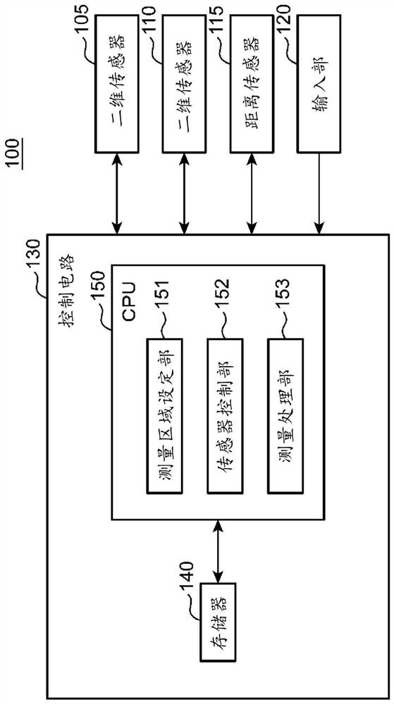
[0033] figure 1 It is a block diagram schematically showing an example of the electrical configuration of the two-dimensional scintillation measurement device of the first embodiment. figure 2 It is a side view schematically showing the measurement state of the two-dimensional scintillation measurement device.
[0034] Such as figure 2 As shown, the two-dimensional flicker measurement device 100 two-dimensionally measures the flicker generated on the display screen of the object 5 to be measured. The measured object 5 is, for example, a device having a display screen such as a liquid crystal display. Such as figure 1 , figure 2 As shown, the two-dimensional scintillation measurement device 100 of the first embodiment includes lenses 10 , 15 , two-dimensional sensors 105 , 110 , a distance sensor 115 , an input unit 120 , and a control circuit 130 . The control circuit 130 includes a memory 140, a central processing unit (CPU) 150, and peripheral circuits (not shown). ...
no. 2 approach
[0076] Figure 9 It is a block diagram schematically showing an example of the electrical configuration of the two-dimensional scintillation measurement device 200 of the second embodiment. The two-dimensional scintillation measurement device 200 of the second embodiment includes a two-dimensional scintillation measurement camera 100A and a personal computer (PC) 210 .
[0077] The two-dimensional scintillation measurement camera 100A has the same configuration as the two-dimensional scintillation measurement device 100 of the first embodiment except that a control circuit 130A is provided instead of the control circuit 130 . That is, the two-dimensional scintillation measurement camera 100A includes lenses 10, 15 ( figure 2 ), two-dimensional sensors 105, 110, distance sensor 115, input unit 120, and control circuit 130A. Control circuit 130A includes memory 140A, CPU 150A, communication interface (communication IF) 160, and peripheral circuits (not shown).
[0078] The m...
no. 3 approach
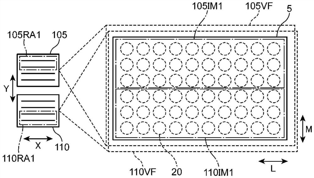
[0084] Figure 10 It is a side view schematically showing the measurement state of the two-dimensional flicker measurement device 100B of the third embodiment. Figure 11 It is a diagram schematically showing the field of view of the two-dimensional sensor and a partial imaging area.
[0085] The two-dimensional scintillation measurement device 100B of the third embodiment has the same configuration as the two-dimensional scintillation measurement device 100 of the first embodiment except that a half mirror 25 is provided instead of the lens 15 . That is, the two-dimensional scintillation measurement device 100B of the third embodiment includes a lens 10, a half mirror 25, two-dimensional sensors 105, 110, and a distance sensor 115 ( figure 1 ), input unit 120 ( figure 1 ) and the control circuit 130.
[0086] The half mirror 25 (corresponding to an example of an optical component) splits the light from the object to be measured 5 into light toward the two-dimensional senso...
PUM
 Abstract
Description
Claims
Application Information
 - R&D
- Intellectual Property
- Life Sciences
- Materials
- Tech Scout
- Unparalleled Data Quality
- Higher Quality Content
- 60% Fewer Hallucinations
Browse by: Latest US Patents, China's latest patents, Technical Efficacy Thesaurus, Application Domain, Technology Topic, Popular Technical Reports.
© 2025 PatSnap. All rights reserved.Legal|Privacy policy|Modern Slavery Act Transparency Statement|Sitemap|About US| Contact US: help@patsnap.com