Determination of a change in the refraction error of an eye

A technique for refractive errors and eyes, which is applied in the direction of eye testing equipment, eye examination, comprehensive refractometer, etc., can solve the problem that the reproducibility of choroid is not enough to be able to actually verify the size of the influence

Active Publication Date: 2021-04-30
CARL ZEISS VISION INT GMBH
View PDF6 Cites 1 Cited by
  • Summary
  • Abstract
  • Description
  • Claims
  • Application Information

AI Technical Summary

Problems solved by technology

[0005] However, the reproducibility of layer thickness measurements of the choroid is often insufficient to enable practical verification of the effect sizes stated in the literature, which are approximately 10 µm to 30 µm or up to 50 µm in the case of primates, or up to 50 µm in the case of chickens. down to about 260 µm

Method used


Image

  • Determination of a change in the refraction error of an eye
  • Determination of a change in the refraction error of an eye
  • Determination of a change in the refraction error of an eye

Examples


Embodiment Construction

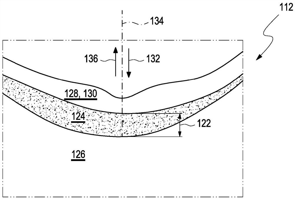
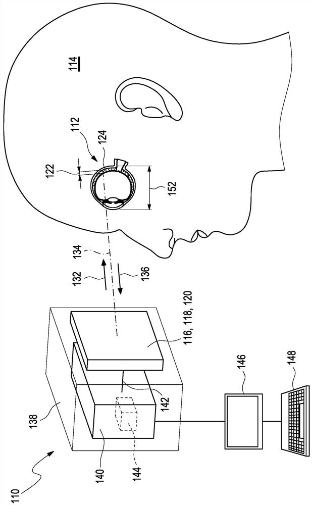
[0088] figure 1 A preferred exemplary embodiment of an apparatus 110 for determining changes in refractive error of an eye 112 of a user 114 is schematically shown. The apparatus 110 comprises a measuring device 116 , preferably an optical measuring device 118 , in particular a device 120 for optical coherence tomography, arranged to capture the layer thickness 122 of the choroid 124 of the eye 112 of the user 114 . However, other types of measuring devices, in particular acoustic or photoacoustic measuring devices, are conceivable. like figure 2 As shown schematically in , the choroidea 124 represents the intermediate layer that is disposed between the sclera 126 and the retina 128, particularly between the sclera 126 and the retinal pigment epithelium layer 130, on the side of the eye 112 away from light incidence. between.

[0089] The apparatus 120 for optical coherence tomography facilitates imaging methods for generating two- or three-dimensional recordings of biolo...


PUM


Abstract

The present invention relates to a method (210), a device (110) and a computer program for determining a refractive error of an eye (112) of a user (114). The method (210) for determining the refractive error of the eye (112) of the user (114), wherein the eye (112) of the user (114) has a choroid (124), comprises the following steps: a) determining at least one value for a layer thickness (122) of the choroid (124) of the eye (112) of the user (114) over at least one region (150) of the choroid (124); and b) determining a value (216) for the change in the refractive error of the eye (112) exclusively from at least two values for the layer thickness (122) of the choroid (124), each of which have been determined at different times for the at least one region (150) of the choroid (124), wherein the at least one region (150) is selected from a nasal perifoveal region (168) or a nasal parafoveal region (166).

Description

technical field [0001] The present invention relates to a method, apparatus and computer program for determining a change in refractive error of a user's eye. Background technique [0002] The prior art has disclosed methods for determining the refractive error of a user's eye. Here, the term "refraction" refers to the refraction of light experienced in the user's eye by a light beam incident inside the eye through the pupil. By providing a number of spectacle lenses with known properties and by guiding the user through a questionnaire process, it is possible to subjectively determine the defocusing of the user's eye and determine, for example, which sphero-cylindrical configuration of the spectacle lens produces substantial compensation for the eye's refractive error and The image quality for the user is thus made as best as possible. Defocusing of the user's eyes can lead to refractive errors (refractive abnormalities) in the user, in particular myopia (nearsightedness) ...

Claims


Application Information

Patent Timeline
Patent Type & Authority Applications(China)
IPC IPC(8): G02C7/02G02B27/00G01M11/02A61B3/14A61B3/10A61B3/028
CPCG02C7/024A61B3/028G02B27/0012A61B3/1015G01M11/0278A61B3/14G01M11/0257G01M11/0207G01M11/0271A61B3/1005A61B3/102A61B3/103G16H50/30G16H30/40A61B3/0025A61B5/0095A61B8/10G06T7/0016G06T2207/10101G06T2207/30041
Inventor A·奥伦多夫K·布雷赫尔S·瓦尔
Owner CARL ZEISS VISION INT GMBH
Why Eureka
Try Eureka